Pulse Building
The Pulse Building application supports four pulse types described in this topic.
This pulse type is defined by rise time, fall time, width, width jitter type, jitter deviation, and modulation type. A trapezoidal pulse has a linear rise and fall time with a characteristic shape shown in the following figure.
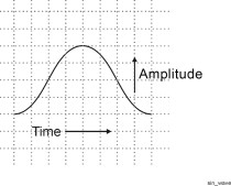
This pulse type is defined by the same parameters that describe a trapezoidal pulse. A raised-cosine pulse has sinusoidal rise and fall times with a characteristic shape as shown in the following figure.
This pulse type is described by user-defined pulse profile data. The pulse is defined by an index number and amplitude value. A pulse can be described using any number of points (index number) representing an amplitude level. The largest amplitude number in the custom profile data table is used to reference all other amplitude data points. The Pulse Building application normalizes the profile amplitude data so that the maximum amplitude is 1.
The Pulse Building software automatically resamples the Custom Profile data if its sampling rate is different from the current Arb Sampling Rate. The current Arb Sample rate is available in the Waveform > General tab.
There are two ways to specify custom profile data. These are described below.
Manually - Add new items (data points) by clicking Add or Insert in the Pulse Config tab. The Add option adds the specified number of new items to the end in the Profile Data table. The Insert option inserts a single new item after the item currently selected in the Profile Data table.
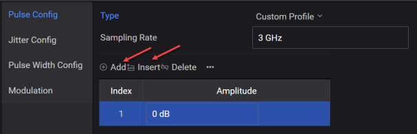
Once new items are entered, you can set amplitude levels that define each sample point.
To delete items, select the item from the table and then click Delete.
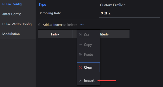
Import - This menu option opens the Open File dialog that allows you to import a .txt file containing custom profile values into the Profile Data table.
Custom profile data can contain modulation. You can also add modulation by selecting a modulation from the Modulation Type drop-down list box. If a step modulation such as FM Step is used, the time duration for the total number of steps must equal the on time for the pulse. Refer to the section on modulation types for more information.
The pulse width, measured from the first data point to the last data point, should equal the maximum index number / sample rate. For example, if the maximum index number is 10 and the sample rate is 10 MHz, then the pulse width should be equal to 1000 ns.
The Pulse Building software automatically resamples the Custom Profile data as necessary to preserve the shape of the user-provided data and minimizes distortion at the end points. However, automatic re-sampling can result in a waveform that won't fit into Arb memory.
This pulse type is a user-defined pulse definition described by an index with I and Q values. A pulse can be described using any number of points. Each index point represents an I and Q value. The software automatically re-samples the custom I/Q data to match the current Arb sampling rate.
The pulse represented by the custom I/Q data can contain complex modulation, frequency offsets, and even complex envelope shapes. In addition, the built-in modulation can be applied to the custom I/Q data.
The re-sampling is accomplished using an FFT and IFFT. The process is designed to preserve the shape of the user provided data and minimize distortion at the end points. The amount of re-sampled data required is calculated as follows:
datanew = Round(datauser * SRpattern/SRuser)
where
datanew = the amount of re-sampled data needed by the application
datauser = the original amount of user custom I/Q or profile data
SRuser = the original user data sample rate
SRpattern = the current pattern sample rate
Some time/frequency error can be introduced by the re-sampling. This is caused when the re-sampling results in a fractional part of a sample point. It is not possible to generate fractional parts of a sample point, so the fraction is rounded to the closest whole number. The time frequency error is introduced during the rounding. The amount of error can be determined by comparing the original signal period with the re-sampled signal period:
Re-sampled signal period = datanew/SRpattern
Original signal period = datauser/SRuser
There are two ways to enter custom I/Q data: manually, by entering data into the I/Q Data table or using the Import option to read data from an external file.
Manually - Add new items (I/Q data points) by clicking Add or Insert in the Pulse Config tab. The Add option adds the specified number of new items to the end in the I/Q Data table. The Insert option inserts a single new item after the item currently selected in the I/Q Data table.
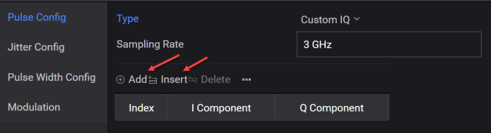
Once new items are added, manually enter I and Q values into the I/Q Data table.
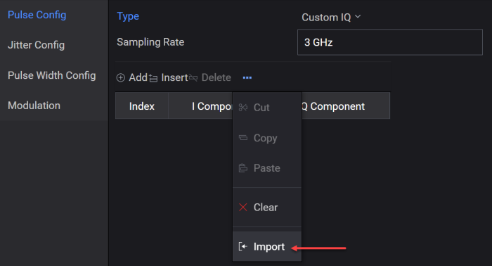
Import - This menu option opens the Open File dialog that allows you to import a .txt file containing IQ pairs and enters these values into the I/Q Data table.
Custom I/Q data can represent a simple pulse profile or complex modulated pulse. You can also add modulation to the custom I/Q data by selecting a modulation format from the Modulation Type drop-down list box. Modulation is applied from the first point of the custom I/Q data through the last point of data. If a step modulation such as FM Step is used, the time duration for the total number of steps must equal the on time for the pulse. Refer to the section on modulation types for more information.