![]()
![]()
Calibration accuracy is affected by the type of calibration, quality of the calibration standards, and the care with which the calibration is performed. This section provides additional information about how to make accurate calibrations.
Learn how to determine the validity of your calibration.
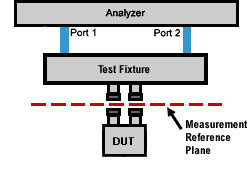
Most measurement setups will NOT allow you to connect a device under test (DUT) directly to the VNA front panel test ports. More likely, you would connect your device to test fixtures, adapters, or cables that are connected to the VNA.
A calibration takes place at the points where calibration standards are connected during the calibration process. This is called the measurement reference plane (see graphic). For the highest measurement accuracy, make the calibration reference plane the place where your DUT is connected. When this occurs, the errors associated with the test setup (cables, test fixtures, and adapters used between the analyzer ports and the reference plane) are measured and removed in the calibration process.

Normally, a calibration is performed using a calibration kit that contains standards with connectors of the same type and sex as your DUT.
However, your calibration kit may not always have the same connector type and gender as your device. For example, suppose your device has 3.5mm connectors, but you have a Type-N calibration kit. If you use an adapter to connect the Type-N standards to the 3.5mm test port, then the adapter becomes part of the calibration and NOT part of the test setup. This will result in significant errors in your reflection measurements.
The Select DUT Connectors and Cal Kits dialog box offers a data-based model and a polynomial model for the newest high-frequency cal kits. See VNA Accessories. The data-based models provide higher accuracy for describing calibration standards than the polynomial models. It is RECOMMENDED that the data-based model be used if the most accurate results are desired.
|
|
Data-Based Model |
Polynomial Model |
|
How accurate is the model? |
Provides highest calibration accuracy. Eliminates the errors that can be the result of polynomial model approximations. |
Provides high calibration accuracy. |
|
How does the model define calibration standards? |
Uses S-Parameter measurements. |
Uses traditional four-term polynomial calibration standard modeling parameters. |
|
How do I manually edit the definitions of the calibration standards when using the model? |
Use the Advanced Modify Cal Kit function. |
Use the Advanced Modify Cal Kit function. |
|
How do I use the Calibration Wizard with the model? |
Use only the SmartCal (Guided) Calibration method. |
Use the SmartCal (Guided) or the Unguided Mechanical Calibration methods. |
Learn about the “Expanded Math” feature.
To attain the most accurate error correction, do NOT change the power level after a calibration is performed. However, when changing power within the same attenuator range at which the measurement calibration was performed, S-parameter measurements can be made with only a small degradation of accuracy. If a different attenuator range is selected, the accuracy of error correction is further degraded.
To check the accuracy of a calibration, see Validity of a Calibration.
Use the port extensions feature after calibration to compensate for phase shift of an extended measurement reference plane due to additions such as cables, adapters, or fixtures.
Port extensions is the simplest method to compensate for phase shift, mismatch, and loss of the path between the calibration reference plane and the DUT.
Learn how to apply port extensions.
Learn about characterizing a test fixture.
The isolation portion of a calibration corrects for crosstalk, the signal leakage between test ports when no device is present. When performing an UNGUIDED 2-port calibration, you have the option of omitting the isolation portion of the calibration.
Note: Isolation can be performed on a Smart (Guided) Calibration ONLY
The uncorrected isolation between the test ports of the VNA is exceptional (typically >100dB). Therefore, you should only perform the Isolation portion of a 2-port calibration when you require isolation that is better than 100dB. Perform an isolation calibration when you are testing a device with high insertion loss, such as some filter stopbands or a switch in the open position.
The isolation calibration can add noise to the error model when the measurement is very close to the noise floor of the analyzer. To improve measurement accuracy, set a narrow IF Bandwidth.
Isolation is measured when the Load standards are connected to the VNA test ports. For best accuracy, connect Load standards to BOTH test ports each time you are prompted to connect a load standard. If two Loads are not available, connect the untested VNA port to any device that will present a good match.
When calibrating for a non-insertable device, you must choose a method to calibrate for the THRU error terms. This can have a significant effect on measurement accuracy. Learn more about choosing a thru method.
Last Modified:
|
18-May-2016 |
First Release. |