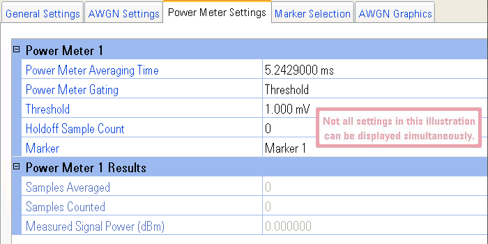
This topic describes the settings for the standard power meter feature. See Output Power Meter Basics for information on standard power meters and sequenced power meters.

This button toggles the power meter measurement on or off while the system is playing. This button becomes inactive (grayed out) when playback is stopped.
|
|
Each signal that goes into an output block has its own uniquely numbered power meter. Each power meter is numbered to coincide with the numbering of the input channel it measures (see the block diagram for a visual representation of your configuration). |
Range:
20 ns to 2748.779069 s
Default Value: 5.2429000 ms
Resolution: 1 ns
Sets the length of time to collect power meter samples and average them to calculate the Measured Signal Power.
|
|
This setting does not wait for valid samples to appear before it starts running, so it is possible to set the power meter measurement so that no valid samples are measured (e.g., with a low duty-cycle waveform and a short measurement time, in which case there is a high probability that the power meter result with be -276 dBm). Increasing the power meter measurement time will ensure the capture of valid samples in the measurement. |
Choices:
Threshold, Marker
Default Value: Threshold
Selects which reference to use for sample selection in determining the waveform's baseband output power. An illustration showing both Power Meter Gating choices can be viewed at Power Calibration Graphics.
Threshold
This choice allows you to set a threshold level to tell the PXB when to
measure the input waveform. Each waveform sample is compared to the specified threshold level. When the sample level meets or exceeds
the threshold level, the voltage for the waveform sample is used to determine
the baseband output power. When a waveform sample's value is less than
the threshold level, the power meter does not use that sample in the calculation. Use this for bursted signals when you want to measure the power of the entire burst.
Marker
This choice uses a marker, identified by the Marker selection, to tell the PXB when to measure the
input waveform. When the marker is turned on for a given sample, the level for that
sample is used to determine the baseband output power. When the marker
is turned off, the power meter does not use that sample in the calculation. The marker criteria is set using the Marker Generation (BBG) tab. Use this for bursted signals when you want to measure only a subsegment of the burst.
Range:
0 to 1.414214 V
Default Value: 1 mV
Resolution: 1 µV
Dependency: Displayed only when Power Meter Gating is set to Threshold
Defines the minimum power for a waveform sample to be used in the power measurement. An illustration showing an example of using a threshold can be viewed at Power Calibration Graphics.
Range:
0 to 65,535 (216–1)
Default Value: 0
Resolution: 1
Dependency: Displayed only when Power Meter Gating is set to Threshold
Specifies the number of consecutive waveform samples that must meet or exceed the threshold voltage level before the waveform sample is used to determine the baseband output power. If the number of consecutive waveform samples is not met, the sample voltages are not used. This setting is useful if the waveform has an inconsistent structure or to eliminate glitches. An illustration showing an example of using Holdoff Sample Count can be viewed at Power Calibration Graphics.
Choices:
Marker 1, Marker 3, Marker 4
Default Value: Marker 1
Dependency: Displayed only when Power Meter Gating is set to Marker
Sets the marker used to select the samples to measure. An illustration showing an example of using a marker for power meter control can be viewed at Power Calibration Graphics.
Default Value: 0
Resolution: 1 Sample
Displays the number of samples that were used in calculating the average baseband output power.
Default Value: 0
Resolution: 1 Sample
Displays the total number of samplesduring the measurement.
Range:
-276 to 20 dBm
Default Value: 0 dBm
Displays the RMS baseband output power.
General
Settings
Marker Settings