Real Time
Configuring the Waveform Setup View
Select a Predefined Carrier Configuration
-
In the  tree view,
select .
tree view,
select .
-
Click the predefined carrier configuration setup button,
located above the summary table.
-
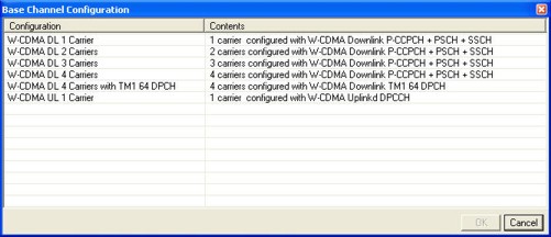
From the dialog box
that appears, select a multiple carrier configuration.
Notice that you have five downlink selections
(single carrier to four carriers) and a single uplink carrier selection.
The selected predefined configuration appears in the carrier configuration
summary table.
You can change the predefined configuration for a carrier from the and tree view
selections.
In this example a four carrier downlink configuration
was selected.
If you select another predefined carrier setup,
it replaces all carriers showing in the configuration summary table.
Add a Carrier
You have the option of adding either a downlink or uplink carrier to
the current carrier selection showing in the configuration summary table.
This process assumes that a multicarrier configuration
appears in the configuration summary table as performed in the previous
procedure "Select
a Predefined Carrier Configuration."
-
In
the configuration summary table, highlight the second carrier.
-
Click
the add new carrier button.
-
Select
either an uplink or downlink carrier from the drop-down menu.
Notice that the software adds the new carrier
above the highlighted carrier. The new carrier's channel configuration
is different from the channel configuration for the carriers selected
in the predefined carrier setup button.
Delete a Carrier
The software provides the convenience of deleting a single carrier or
multiple carriers.
-
In the configuration summary table, highlight the carrier
or carriers that require deletion.
To select multiple carriers, use the keyboard
key operation to select
carriers in succession (a group) or the
key to select multiple individual carriers.
-
Click the delete button
above the configuration summary table.
Waveform Attributes
It is best to configure these parameters after setting the channel and
carrier parameters, since they determine the waveform length, which also
determines the maximum number of usable marker points for a waveform.
-
Enter general
information about the waveform
-
Optionally configure the waveform's markers.
-
Select
the marker number (
cells).
-
Click
on the more detailicon
located at the far right of the row.
-
Configure
the marker in the Marker
Source Selection dialog box that appears.
The signal generator outputs a marker signal from
the rear-panel EVENT 1-4 outputs based on the marker bit settings. The
EVENT output number corresponds to the marker number. For example, causes the signal generator to output a marker
signal on the EVENT 1 output. For more information on markers and the
rear panel EVENT outputs, see the signal generator's User
Guide.
Related Topics
Waveform
Setup
Waveform
Graph
CCDF
Graph
Marker Selection Dialog Box
Configuring the Carrier View
Configuring the Channel Setup View