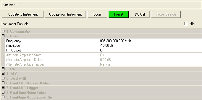
The following figure is a sample of all the supported instruments, so some parameters may not apply to your instrument and others may not be shown.
Signal Generator Instrument Controls

|
2. Basic (ESG/EXG/MXG/PXG) |
2. Basic (PXB) |
2. Basic (EXT) |
|---|---|---|
|
|
||
|
|
||
|
|
|
|
|
|
|
Range: for frequency range values, see the instrument's data sheet
Enter a value to set the instrument’s output frequency. Use abbreviations for faster entry (example: 1g = 1.000000000000 GHz).
If the frequency you enter here is within the frequency range determined by the Frequency Band and Transmit Device settings in the Waveform Setup Node, the corresponding ARFCN number is automatically entered in the Waveform Setup node. If the frequency you enter here falls outside the frequency range determined by the current Frequency Band and Transmit Device settings in the Waveform Setup node, the ARFCN cell in the Waveform Setup node displays --- and the Instrument node frequency setting is the active frequency.
Choice: On | Off
Default: On
Double-click or use the drop-down menu to control the signal generator’s Alternate Amplitude Delta.
This parameter is not available with all instrument model numbers and may be grayed out.
Choice: On | Off
Default: On
Double-click or use the drop-down menu to control the signal generator’s Alternate Amplitude state.
This parameter is not available with all instrument model numbers and may be grayed out.
Choice: On | Off
Default: On
Double-click or use the drop-down menu to control the signal generator’s Alternate Amplitude Trigger.
This parameter is not available with all instrument model numbers and may be grayed out.
Range: for amplitude range values, see the instrument's data sheet
Enter a value to set the instrument’s output amplitude in dBm.

Range: 1 to 16
Default: 1
When you establish a connection between the Signal Studio software and the PXB, Signal Studio recognizes the number of baseband generators (BBGs) in the currently loaded PXB configuration. Signal Studio creates a waveform file (Ant0, Ant1, Ant2, and so on) for each antenna configured in the System Configuration Wizard. The default behavior is for Signal Studio to download waveform file Ant0 to BBG1 in the PXB, waveform file Ant1 to BBG2, and so on. In the Baseband Channel Assignment cell, the default BBG assignments are displayed as a comma-separated list (1,2).
The Baseband Channel Assignment parameter enables you control the assignment of each waveform file to a specific BBG resource, rather than accepting the default. You can assign Ant0 to BBG2 and Ant1 to BBG1 by making the corresponding change to the comma separated list (2,1).
PXB Baseband Generator and Channel Emulator

Choice: -110 to -30 dB
Default: -10 dB
In a typical MIMO system, the average power of the signal transmitted by each antenna is different than the average power transmitted by the other antennas. For example, a difference in average power can be caused by preambles or other reference signals that are present on some antennas and not on others.
When connected to a PXB Baseband Generator and Channel Emulator, Signal Studio provides a separate Relative Amplitude cell for each antenna to display this difference in average power. For example, if you set up a two-antenna configuration in the System Configuration Wizard, the software displays two Relative Amplitude cells.
When you generate the waveform, the software sets the power in the Relative Amplitude cells based on the current waveform settings. The value in each Relative Amplitude cell represents the power in the corresponding baseband generator (BBG) on the PXB relative to the power in the other BBGs.
Choice: Off | On
Default: On
Double-click or use the drop-down menu to turn the instrument’s RF output or .
Choice: RF Out | RFIO 1 | RFIO 2
Default: RF Out
Double-click or use the drop-down menu to control the instrument’s RF output port.
The RF Output Port selected
effects the range of the output amplitude. Refer to  Table.