
|
1. Configuration |
|---|
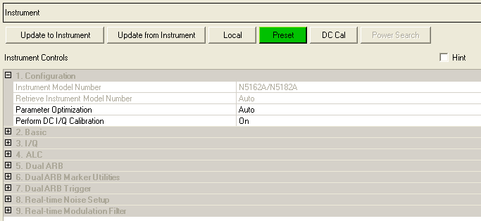
Displays the model number of the connected instrument (read only). The parameters that are available in the Instrument node are determined by the Instrument Model Number.
When active, you can select manual or automatic retrieval of the connected instrument's model number.
Double-click or use the drop-down menu to enable or disable parameter optimization.
– automatically overrides the current instrument settings and provides optimized settings.
– parameter optimization is not used.
Parameter Optimization selects the appropriate marker for RF control and sets the appropriate marker routing to the instrument control. When Parameter Optimization is set to , Marker 3 and Marker 4 source selection in WFMn and the marker routing selected in Dual ARB Marker Utilities are overridden.
To manually set Marker 3 and Marker 4 source, the marker routing, or both, set Parameter Optimization to .
Double-click or use the drop-down menu to enable or disable automatic DC I/Q calibration.
– The signal generator performs a DC I/Q calibration after downloading a waveform.
– The signal generator does not perform a DC I/Q calibration after downloading a waveform.
In GSM and EDGE, the Global Phase and EVM measurement results are influenced by the amount of IQ offset in the signal.
Performing a DC I/Q calibration minimizes the error contributed by the signal generator. In general, a DC I/Q calibration is recommended after a change in RF frequency or amplitude, but note that some measurements, like spectrum distortion, may not be affected by this calibration, and others may include an error from the DUT that dominates the final reading. In such cases, you can reduce test time by disabling the DC I/Q calibration.