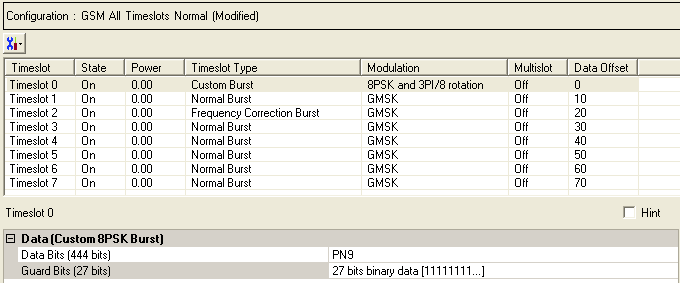
To open the Data node, click Data in the tree view. The figure below shows the Data node.
|
Data (Custom GMSK Burst) |
|---|
Click  to display a drop-down menu in which you
can copy
a timeslot configuration
from one timeslot to another.
to display a drop-down menu in which you
can copy
a timeslot configuration
from one timeslot to another.
Use the Data window to define the bits in the bursts. The cells displayed in the Data section are determined by the burst type (Timeslot Type) for the selected timeslot as defined in the Timeslots window. In the window shown above, Timeslot 1 is selected so the data cells provided are for setting up a Custom EDGE Burst (the 8-PSK and 3PI/8 rotation modulation indicates that this is an EDGE burst).

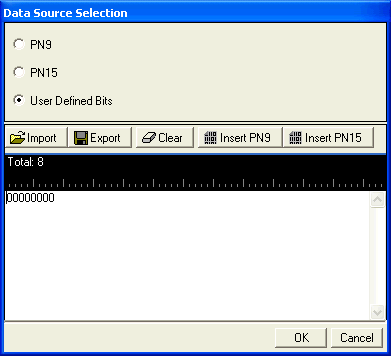
Click the Details button  in this cell to open the
  Data Source Selection
window. Select ,
or to use for
the data bits.
Data Source Selection
window. Select ,
or to use for
the data bits.
Click the Details button in this cell to open the Data Source Selection
window.
When the Timeslot Timing Mode is set to , the Guard Period is defined as follows:
If the Custom EDGE Burst is in timeslot 0,2,3,5,6 or 7, the guard period has 24 bits with a default value of X"FFFFFF".
If the Custom EDGE Burst is in timeslot 1 or 4, the guard period has 27 bits with a default value of X"7FFFFFF".
When the Timeslot Timing Mode on the Carrier node is , the Guard Period is defined as follows:
The guard period in all timeslots has 27 bits with a default value of X”7FFFFFF”.
 Click
Click  Click
Click  Click
Click  Click
Click