To open the Timeslot node, click Timeslot in the tree view. The figure below shows the Timeslot node.
Click  to open a window with a list of pre-defined
timeslot configurations for GSM/EDGE/EGPRS2-A
or EGPRS2-B.
To replace the current configuration in the Timeslot node with one of
these pre-defined configurations, select the desired configuration and
click or double-click the desired
configuration.
to open a window with a list of pre-defined
timeslot configurations for GSM/EDGE/EGPRS2-A
or EGPRS2-B.
To replace the current configuration in the Timeslot node with one of
these pre-defined configurations, select the desired configuration and
click or double-click the desired
configuration.
Click  to open a drop down menu
from which you can:
to open a drop down menu
from which you can:
copy a timeslot configuration from one timeslot to another
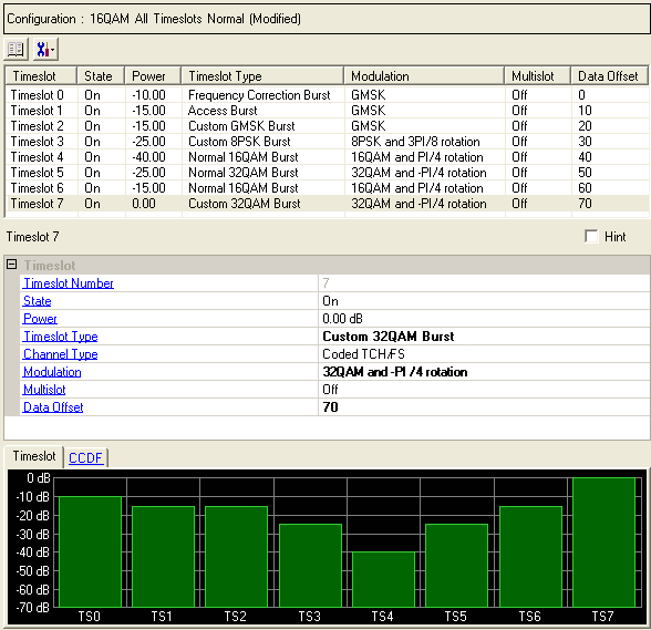
Select a timeslot from the list at the top of the window. The parameters that you configure at the bottom of the window apply to the selected timeslot.
Displays the number of the selected timeslot. The parameters you set apply to this timeslot.
Choice: On | Off
Default: On
Double-click or use the drop-down menu to set the state of the timeslot or .
Range: –70 to 0 dB.
Default: 0 dB
Enter a value to set the timeslot power.
Timeslot Type (GSM/EDGE/EGPRS2-A)
Choice: Normal GMSK Burst | Normal 8PSK Burst | Frequency Correction Burst | Synchronization Burst | Dummy Burst | Access Burst | Custom GMSK Burst | Custom 8PSK Burst | Normal 16QAM Burst | Normal 32QAM Burst | Custom 16QAM Burst | Custom 32QAM Burst
Default: Normal GMSK Burst
Double-click or use the drop-down menu to select the timeslot type.
Timeslot Type (EGPRS2-B)
Choice: HSR QPSK Burst | HSR 16QAM Burst | HSR 32QAM Burst | Custom QPSK Burst | Custom 16QAM Burst | Custom 32QAM Burst
Default: HSR QPSK Burst
Double-click or use the drop-down menu to select the timeslot type.
Displays the modulation type (appropriate to GSM/EDGE/EGPRS2). This setting is not editable.
Choice: On | Off
Default: Off
Double-click the cell or use the drop-down menu to set the multislot state or . When multislot is on, the power level is maintained between timeslots.
This parameter is not active for symbol bit output.
Range: 0 to 32767
Default: 0 (timeslot 0) to 70 (timeslot 7) for single carrier waveforms.
The default data offset continues to increment by 10 for each successive timeslot in subsequent carriers when a multi-carrier configuration is selected from the Pre-defined Carrier Configurations. (For example, in Carrier 2 the default for timeslot 0 is 80, for timeslot 1 is 90, and so on.) If carriers are added manually, the default data offset for timeslots starts at 0 for every carrier.
Enter a value to set a data offset for the selected timeslot.