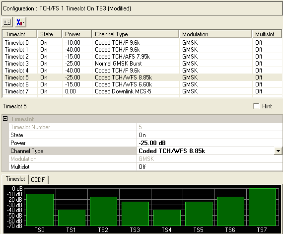
To open the Timeslot node, click Timeslot in the tree view.
The figure below shows the Timeslot node.

|
Timeslot |
|---|
Click  to open a window with a list of pre-defined
timeslot configurations for Advanced GSM/EDGE/EGPRS2-A,
Half
Rate GSM/EDGE/EGPRS2-A, Advanced EGPRS2-B carriers,
or Control
Carrier. To replace the current configuration in the Timeslot node
with one of these pre-defined configurations, select the desired configuration
and click or double-click the
desired configuration.
The Advanced GSM/EDGE/EGPRS2-A, Advanced EGPRS2-B carriers, Advanced EGPRS2-B, and Advanced Control carriers require Option QFP.
Click  to open a drop down menu
from which you can:
copy a timeslot configuration from one timeslot to another
Select a timeslot from the list at the top of the window. The parameters that you configure at the bottom of the window apply to the selected timeslot.
Displays the number of the selected timeslot. The parameters you set apply to this timeslot.
Choice: On | Off
Default: On
Double-click or use the drop-down menu to set the state of the timeslot or .
Range: –70 to 0 dB.
Default: 0 dB
Enter a value to set the timeslot power.
This cell requires Option QFP and the selection of one of the  Advanced carriers.
Double-click or use the drop-down menu to select the channel type, which
is dependent upon the selected advanced carrier:
Choice: Coded TCH/FS | Coded TCH/WFS 12.25k | Coded TCH/WFS 8.85k | Coded TCH/WFS 6.60k | Coded CS-1 | Coded CS-4 | Coded Downlink MCS-1 | Coded Uplink MCS-1 | Coded Downlink MCS-5 | Coded Uplink MCS-5 | Coded Downlink MCS-6 | Coded Uplink MCS-6 | Coded Downlink MCS-7 | Coded Uplink MCS-7 | Coded Downlink MCS-8 | Coded Uplink MCS-8 | Coded Downlink MCS-9 | Coded Uplink MCS-9 | Coded E-TCH/F43.2 | Coded UAS-11 | Normal GMSK Burst | Normal 8PSK Burst | Normal 16QAM Burst | Normal 32QAM Burst
Default: Coded TCH/FS
Choice: Coded UBS-6 | Coded UBS-8 | Coded UBS-11 | HSR QPSK Burst | HSR 16QAM Burst | HSR 32QAM Burst
Default: Coded UBS-6
Choice: FCCH+SCH+BCH+CCCH | FCCH+SCH+BCCH+CCCH+SDCCH/4(0…3)+SACCH/C4(0…3)
Default: FCCH+SCH+BCH+CCCH
When Standard Combined BCH Channel is selected, the contents are different for different frames in a multiframe. The reason is that different bursts (FCCH, SCH, BCCH, SDCCH, SACCH and CCCH) are time multiplexed together for BCH channel according to the standards. But, if the channel type is not Standard Combined BCH Channel, every timeslot on frames has same timeslot configuration type.
The default channel type is different for different timeslots. For timeslot 0, the channel type is Standard Combined BCH Channel. For all the other timeslots, the default channel types are Dummy Burst.
The
default channel types for different timeslots follow the 3gpp standards.
But, other channel types are provided to enable greater measurement flexibility.
The channel types used in the Control Channel, don’t contain any coded
TCH or coded PDTCH type, to avoid excessive traffic channel information
on Control Channel. If it is desired to mix BCH and TCH/PDTCH together,
use multi-carriers.  Example:Control Channels as BCH, and Advanced2-A
as TCH or PDTCH.
Displays the modulation type (appropriate to GSM/EDGE/EGPRS2). This setting is not editable.
Regardless of the Channel Type, when using Control Channels, always use GMSK as the modulate type for the Control Channel.
Choice: On | Off
Default: Off
Double-click the cell or use the drop-down menu to set the multislot state or . When multislot is on, the power level is maintained between timeslots.