A waveform is made up of one or more carriers, each of which is modulated with GMSK, 3p/8 PSK, QPSK, 16QAM, 32QAM or a mixture of the various modulation types. The modulation data can take one of two forms, Framed or Continuous. In a Framed carrier, data is associated with one of eight individual timeslots. A Framed carrier can use only a Framed configuration and a Continuous carrier can use only a Continuous configuration.
This table enables you to view and change waveform attributes. You can add or delete waveforms using the buttons above the table (see descriptions below).
Use the button  to add a waveform
above the currently selected waveform in the table. Select from the
to add a waveform
above the currently selected waveform in the table. Select from the  pre-defined carrier configurations.
The software allows a maximum of four waveforms, which are shown in the
tree view
as WFMn.
pre-defined carrier configurations.
The software allows a maximum of four waveforms, which are shown in the
tree view
as WFMn.
Use the button  to delete the currently
selected waveforms in the setup table. To select multiple waveforms, hold
down the
key while you click the desired waveforms or use the mouse and the key to select a group of waveforms.
to delete the currently
selected waveforms in the setup table. To select multiple waveforms, hold
down the
key while you click the desired waveforms or use the mouse and the key to select a group of waveforms.
Enter an alpha-numeric waveform file name of up to 22 characters. The name can include spaces and the following special characters: _ $ & # + - [ ]. If you enter a name with more than 22 characters, the software truncates the name to 22 characters when you click outside of the cell. The default name is .
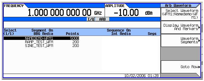
The name you define here is displayed on the instrument
when you download the waveform.
is shown as an example in the signal generator
display.
Enter an alpha-numeric comment of up to 32 characters. The comment resides in the file header and can include spaces and special characters.
Choice: Off | On
Default: Off
Double-click or use the drop-down menu to turn sequencing capability or . When you select , Sequence appears in the tree view below Waveform Setup. Click in the tree view to open the Sequence node in which you can configure a waveform sequence.
Range: Dependent upon frequency band setting.
Default: 1
Enter the absolute radio frequency channel number (ARFCN). The combination of ARFCN, Frequency Band, and Transmit Device determine the Frequency setting.
If you enter a frequency in the Instrument node that is within the frequency range determined by the Frequency Band and Transmit Device settings in the Waveform Setup Node, the corresponding ARFCN number is automatically entered in the Waveform Setup node. If you enter a frequency setting in the Instrument node that is outside the frequency range determined by the current Frequency Band and Transmit Device settings, the Instrument node frequency setting is used and the ARFCN cell displays ---.
Choice: P-GSM 900 | E-GSM 900 | R-GSM 900 | DCS 1800 | PCS 1900 | GSM 450 | GSM 480 | GSM 850 | GSM 750
Default: P-GSM 900
Select a frequency band from the drop-down list. The combination of ARFCN, Frequency Band, and Transmit Device determine the Frequency setting.
Choice: Mobile | Base
Default: Base
Select a Mobile or Base transmit device. The combination of ARFCN, Frequency Band, and Transmit Device determine the Frequency setting.
The combination of ARFCN, Frequency Band, and Transmit Device determine the Frequency setting.
If you enter a frequency in the Instrument node that is within the frequency range determined by the Frequency Band and Transmit Device settings in the Waveform Setup Node, the corresponding ARFCN number is automatically entered in the Waveform Setup node. If you enter a frequency setting in the Instrument node that is outside the frequency range determined by the current Frequency Band and Transmit Device settings, the Instrument node frequency setting is used and the ARFCN cell displays ---.
Choice: On | Off
Default: Off
Turn the symbol bit output mode on or off. This mode is active when 16800/16900 logic analyzers, which includes N5343A DigRF solution, are the selected hardware. When this mode is set to On, a new carrier, EGPRS2-A Symbol bit output, is added which provides fully coded symbols for DigRF.
No additional carriers can be added when using this mode. Turning this mode off returns to the default waveform set up configuration.