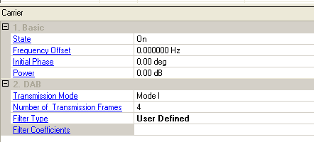

Choice: On | Off
Default: On
Double-click or use the drop-down menu to set the state of the carrier ON or OFF.
Range: -40 to 40 MHz
Default: 0.000000 Hz
Set the frequency offset for the carrier relative to the signal generator’s frequency setting.
Range: 0.00 to 359.00 deg
Default: 0.00 deg
Set the initial phase of the carrier.
Range: -50.00 to 0.00 dB
Default: 0.00 dB
Set the carrier’s power relative to the signal generator’s amplitude setting.
Choice: ModeI |ModeII | ModeIII | ModeIV
Default: ModeI
Set the transmission modes (i.e. I, II, III and IV), which are defined to allow the system to be used for different network configurations and a range of operating frequencies. Four transmission modes have 4 different carrier numbers: 1536, 768, 384 and 192.
|
Transmission mode |
Duration of transmission frame |
Number of FIBs per transmission frame |
Number of CIFs per transmission frame |
|---|---|---|---|
|
I |
96 ms |
12 |
4 |
|
II |
24 ms |
3 |
1 |
|
III |
24 ms |
4 |
1 |
|
IV |
48 ms |
6 |
2 |

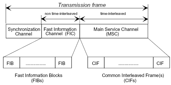
In our Signal Studio product, FIG in the FIB (Fast Information Channel) could be configured with flexibility - pre-defined or user-defined, and more information are available on FIG Configuration.
The MSC is comprised of Common Interleaved Frames (CIFs), which contains 55 296 bits. The smallest addressable unit of the CIF is the Capacity Unit (CU), comprising 64 bits.
Therefore, the CIF contains 864 CUs, which shall be identified by the CU addresses 0 to 863.
For more information on the CIF Structure, please check CIF structure.
Range: 1 to 10000
Default: 4
Set the number of transmission frames. Please be aware of that, by default when the is , the will automatically be set to 60, which could later be modified by users; however, when you select in Audio Service Component Type of the certain service component, and change the to a value other than 60, there might be a waveform discontinuity problem.
Choice: None | Ideal Lowpass | User Defined
Default: None
Set the filter type.
A low-pass filter is a filter that passes low-frequency signals but reduces the amplitude of signals, or called attenuates, with frequencies higher than the cutoff frequency. Usually an is recommended to acquire a smooth spectrum.
Set the filter coefficients.
This parameter is valid only when Filter Type is User Defined.