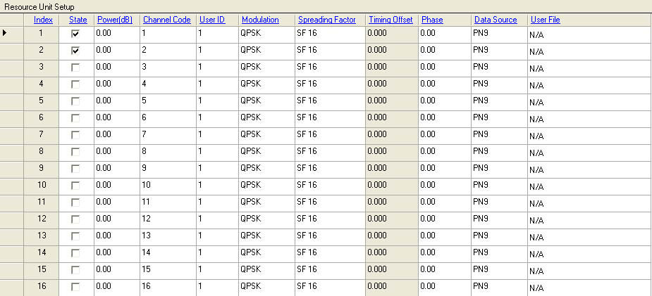

This cell displays the index of the Resource Unit (RU) for this timeslot
Enable or disable the selected RU.
Right-clicking the column header of State, a popup menu will appear to facilitate you to make proper setup.
All-Selected - Enable all RU's state.
All-Cleared - Disable all RU's state.
Range: –60 to 0 dB.
Default: 0 dB
Enter a value to set the RU power relative to other RU. The CDP graph displays the normalized power of each RU in each timeslot after you generate the waveform. Refer to the Power Setting for the power calculation of the carriers, channels/timeslots and RUs.
Right-clicking the column header of Power, a popup menu will appear to facilitate you to make proper setup.
Normalize Power - Normalized the power of the RUs in this timeslot.
All Default Power (0 dB) - Set the power of all RU in this timeslot to 0 dB.
Range: 1 to 16
Default: index of the current RU
Enter a value to set the channel code of the selected RU.
Channel code is coupled with the spreading factor. Channel code can not exceed the spreading factor.
Range: 1 to 16
Default: 1
Enter a value to set the User ID of the current RU.
User ID of the current RU is coupled with the max user number for this timeslot. User ID can not exceed the max user number of the timeslot.
Choices: QPSK | 8PSK | 16 QAM | 64 QAM
Default: 0 dB
Double-click or use the drop-down menu to set the modulation type of the selected RU.
Right-clicking the column header of Modulation, a popup menu will appear to facilitate you to make proper setup.
All QPSK - Set the modulation types of all RUs in this timeslot to QPSK.
All 8PSK - Set the modulation types of all RUs in this timeslot to 8PSK.
All 16QAM - Set the modulation types of all RUs in this timeslot to 16QAM.
Choices: SF 1 | SF 2 | SF 4 | SF 8 | SF 16
Default: SF 16
Double-click or use the drop-down menu to set the spreading factor of the selected RU.
Right-clicking the column header of Spreading Factor, a popup menu will appear to facilitate you to make proper setup.
All SF 16 - Set the Spreading factors of all RUs in this timeslot to 16.
All SF 8 - Set the Spreading factors of all RUs in this timeslot to 8.
All SF 4 - Set the Spreading factors of all RUs in this timeslot to 4.
All SF 2 - Set the Spreading factors of all RUs in this timeslot to 2.
All SF 1 - Set the Spreading factors of all RUs in this timeslot to 1.
Range: –8 to 8 chips
Default: 0 Chips
Enter a value to set the timing offset for the selected RU in this timeslot. If the OSR is equal to 8, 16, 24 or 32, the timing offset values increment by 0.125 chip; If the OSR is set to other values, the timing offset values increment by 1 chip. Physical channels summed in phase produce a high crest factor (high peak-to-average ratio). Offsetting the timing can minimize the crest factor. This cell is read-only for downlink timeslots.
Right-clicking the column header of Timing Offset, a popup menu will appear to facilitate you to make proper setup.
Reset - Reset the timing offset of all RUs in this timeslot to 0.
Timing Offset property is only valid for uplink timeslots. For downlink timeslots, it is read-only. The switching point determines how timeslots 2 through 6 are allocated between uplink and downlink. Timeslots before the switching point are allocated to the uplink; timeslots after the switching point are allocated to the downlink.
Range: –360 to 360 degrees
Default: 0 degree
Enter a value to set the phase rotation for the selected RU in this timeslot. Right-click the column header of Phase, and a popup menu will appear to facilitate you to make proper setup.
Reset: Reset the phase rotation of all RUs in this timeslot to 0 degree.
Choices: PN9 | PN15 | 0, 1 text file | Binary file
Default: 0 dB
Double-click or use the drop-down menu to set the data source for the selected RU.
|
PN 9 |
select continuous PN9 sequence numbers with random initial offset |
|
PN 15 |
select continuous PN15 sequence numbers with random initial offset |
|
0, 1 text |
selects this to load a user-defined 0, 1 text file from a selected location as the data source. When this choice is selected, an Open window is displayed for navigating to and selecting the desired ASCII file (*.txt). |
|
Binary file |
selects this to load a user-defined binary file from a selected location as the data source. When this choice is selected, an Open window is displayed for navigating to and selecting the desired binary file. |
Right-clicking the column header of Data Source, a popup menu will appear to facilitate you to make proper setup.
All PN9 - Set the data source of all RUs in this timeslot to PN9.
All PN15 - Set the data source of all RUs in this timeslot to PN15.
If you select 0, 1 text file or binary file as the data source, this cell displays the path that you load the file from.