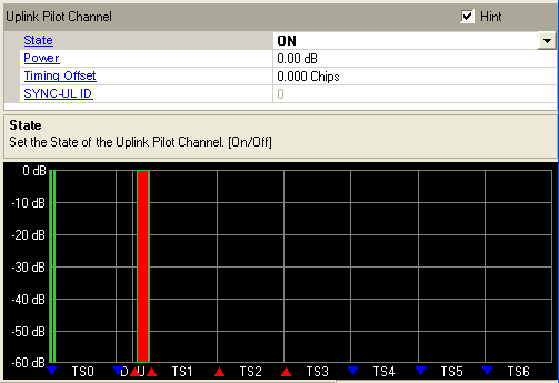

The uplink pilot timeslot/channel is used for initial synchronization, random access and adjacent cell handoff measurements. There are 256 synchronization codes, which can be divided into 32 groups of 8 codes. The base station receives initial beam forming parameters from this signal. The UpPTS is 125 ms long.

UpPTS - Uplink Pilot Timeslot
Choice: ON | OFF
Default: On
Double-click or use the drop-down menu to set the state of the uplink pilot timeslot or .
Range: –60 to 0 dB.
Default: 0 dB
Enter a value to set the uplink pilot timeslot power. The CDP graph displays the normalized power of each RU in each timeslot after you generate the waveform. Refer to the Power Setting for the power calculation of the carriers, channels/timeslots and RUs.
Range: –96 to 24 chips
Default: 0.000 Chips
Enter a value to set the transmit timing offset for UpPTS. If the OSR is equal to 8, 16, 24 or 32, the timing offset values increment by 0.125 chip; If the OSR is set to other values, the timing offset values increment by 1 chip. Physical channels summed in phase produce a high crest factor (high peak-to-average ratio). Offsetting the timing can minimize the crest factor.
Range: 8 * SYNC-DL ID to 8 * SYNC-DL ID + 7
Default: 0
Enter a value to set the uplink synchronization code used in UpPTS. SYNC-UL ID belongs to the code group determined by the SYNC-DL ID.