Fading effect can be applied to SISO signals for setups with one instrument,
or to STC/MIMO signals for setups with two instruments. Signal Studio
for Mobile WiMAX can create the waveforms representing either the signals
at the transmitter antennae or the receiver antennae of a STC/MIMO system.
Click the
links to see the diagrams for a  2x1 STC
system,
a 2x2 MIMO
system
and a UL collaborative SM 1x2 system.
2x1 STC
system,
a 2x2 MIMO
system
and a UL collaborative SM 1x2 system.
Choices: On, Off
Double-click or use the drop-down menu to enable or disable the fading effect in the waveform.
Choices: Static, Mobile
Double-click or use the drop-down menu to select the fading type to Static multi-path channel model or Mobile channel model with Doppler effects.
Specify the channel carrier frequency, which is used for Doppler effects in the fading simulations. By default, this parameter is equal to the instrument RF output frequency. If the desired output is a baseband signal, use this field to set the appropriate frequency to use for the fading simulation.
Specify the number of base station antennas.
In Single Antenna Downlink mode, this parameter is automatically coupled with the STC type in the DL-PUSC.
If the STC type is set to None, Bs Antenna Number = 1.
If the STC type is Matrix A or Matrix B, Bs Antenna Number = 2. In this case, you can select which antenna (antenna 0 or antenna 1) you wish the output waveform sent to at STC/Collaborative Output Mode
In Single Antenna Uplink mode, this parameter is automatically couple with the Collaborative Burst in UL-PUSC.
If no Collaborative Burst is added, Bs Antenna Number = 1.
If a Collaborative burst is added , Bs Antenna Number = 2; In this case, you can select which antenna (antenna 0 or antenna 1) you wish the output waveform sent to at STC/Collaborative Output Mode
In Multiple Antennae mode (Uplink or Downlink), Bs Antenna Number = 2.
Specify the number of mobile station antennas.
In Single Antenna Downlink mode, this parameter is automatically coupled with the STC type in the DL-PUSC.
If the STC type is set to None, Ms Antenna Number = 1;
If the STC type is Matrix A, Ms Antenna Number can be set to 1 or 2;
If the STC type is Matrix B, Ms Antenna Number = 2; In this case, you can select which antenna (antenna 0 or antenna 1) you wish the output waveform sent to at STC/Collaborative Output Mode
In Multiple Antennae Downlink mode, Ms Antenna Number = 2.
In Uplink mode, Ms Antenna Number = 1.
Click  box to
specify the or
channel parameters
box to
specify the or
channel parameters
For an uplink signal, if a collaborative burst is present and multiple antennae configuration is chosen, ”Channel Parameters (Second)” will also be available so that you can specify channel parameters for the two MS separately.
This parameter is active when Channel Type is set to Static.
Click  on the right of the cell to bring up the
Multi-Path Setting (Static)
window, which enables you to add up to 20 paths with delay, power and
phase impairments to simulate the multi-point reflection experienced in
a real-world WiMAX multipath environment. The editing table was designed
so that you can randomly edit and enable or disable paths as needed for
fine-tuning.
on the right of the cell to bring up the
Multi-Path Setting (Static)
window, which enables you to add up to 20 paths with delay, power and
phase impairments to simulate the multi-point reflection experienced in
a real-world WiMAX multipath environment. The editing table was designed
so that you can randomly edit and enable or disable paths as needed for
fine-tuning.
Note that there are tabs for each channel, for example, channel H10 for the channel from Tx Antenna 1 to Rx Antenna 0.
The following impairments can be made to each path:
Delay (0 to 20000 ns) - A reflected signal bounces off of one or more surfaces before reaching the receiver, resulting in a longer path than the line-of-sight signal. Therefore, the reflected signal experiences some amount of delay, relative to the line-of-sight signal.
Power (–100 to 0 dB) - Power Attenuation occurs with reflected signals as a result of the added distance they travel, compared to the line-of-site signal. Other factors may also contribute to signal power attenuation, such as reflected surface characteristics.
Phase (–360 to 360 Deg) - Signals become distorted as they reflect off of walls or other surfaces or wrap around corners, causing a shift in phase, relative to the line-of-site signal. The user can adjust the phase of each multipoint signal to simulate such distortions.
When enabling multipath configuration, it is best to turn off RF Blanking. Leaving Blanking on can result in partial blanking of any delayed multipaths (see the figure below). To disable RF Blanking, click the in the tree view and set the RF Blanking to None. You can also turn off RF blanking on the instrument after the waveform file has been downloaded.
![]()
Effect of RF blanking on signals with multipoint reflection
Choices: Pedestrian A, Pedestrian B, Vehicular A, Vehicular B, Vehicular A Extended, User Defined
Use this cell to select the channel model, which will be applied to each fading channel. If no correlation is chosen, the channels will be treated as independent channels, and then the faded signals will be summed as shown in the above figures to create the waveforms for each of the receiver antennae. If correlation is chosen, the appropriate MIMO correlation matrix is applied. Thus, each faded waveform will contain portions of the signals from both transmit antennae.
- They are four modified International Telecommunication Union (ITU) channel models to simulate the multipath fading of the channel. The multipath fading is modeled as a tapped-delay line with 6 taps with non-uniform delays. The Classical Doppler spectrum and Rayleigh amplitude distributions are used. For each tap, we use the method of filtered noise to generate channel coefficients with the specified distribution and spectral power density.
- This is the ITU Vehicular A channel model with the delay on the last tap moved from 2150 ns to 10,000 ns, for support of long channel impulse response.
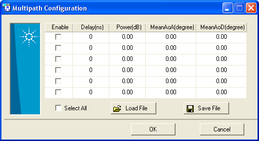
- This allow you to provide your own values for the path delay profile
settings to be used. When you select User Defined, a Multi-paths Setting
cell will show at the next row. Click to open the Multipath
Configuration (Mobile)
window for entering the path settings. Up to six paths are allowed with
delay, power, mean AoA and mean AoD settings for each.
Range: Auto, 0 to 2147483647
Set the random number generation seed of the fading channel. In the default "auto" mode, the fading data will be different each time the waveform is generated. If you want the same fading data each time, change this parameter to a fixed value. Setting the value to 0 is equal to setting it to "auto".
Range: 0.0 to 1000.0
Set the Ricean factor for the first path of the fading channel.
Range: 0.0 to 250.0km/h
Set the speed of the mobile station for the fading channel. This parameter is automatically coupled with the Channel Model.
Choices: No, Low, Medium, High
Double-click or use the drop-down menu to select the channel correlation type.
- The channels will be treated as independent channels, and then the faded signals will be summed as shown in above figures to create the waveforms for each of the receiver antennas.
- Low correlation matrix is applied to create the faded signal. Low correlation is a combination of spatial and polarization correlation. If you select low correlation, you also need to set the BS Antenna Dimension, MS Antenna Dimension and the Polarization Power Ratio.
- Medium correlation matrix is applied to create the faded signal. Medium correlation is a polarization correlation. It is usually obtained from a cross polarized mobile station antenna and a slant cross-polarized base station antenna. If you select medium correlation, you need to set the Polarization Power Ratio.
- High correlation matrix is applied to create the faded signal. High correlation is a spatial correlation. It is usually obtained from an MS ULA with a half-wavelength spacing and BS ULA with four wavelength spacing. If you select high correlation, you also need to set the BS Antenna Dimension and the MS Antenna Dimension.
- User defined correlation matrix is applied to create
the faded signal. You could provide your own values for the correlation
matrix. When you select User Defined, a Correlation Matrix cell will show
at the next row. Click to open the Correlation
Matrix Configuration
window for entering the values.
Range: 0.01 to 10.00
Set the Antennae Spacing at the base station, which is normalized by carrier wavelength.
Range: 0.01 to 10.00
Set the Antennae Spacing at the mobile station, which is normalized by carrier wavelength.
Range: –20 dB to 0 dB
Set the Vertical-to-Horizontal and Vertical-to-Vertical Polarization power ratio.