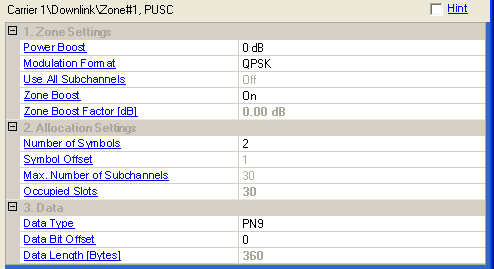

Range: –12 to 9 dB, in 3 dB increments
Double-click or use the pull down menu to set the relative power offset, in dB.
Choice: QPSK, 16QAM, 64QAM
Double-click or use the pull down menu to select a modulation type.
Double-click or use the drop-down menu to turn On or Off.
On - all subchannels are used for this zone.
Off - the subchannels are assigned in the Group Bitmask.
This parameter is not available for the first PUSC zone.
Double-click or use the drop-down menu to turn On or Off.
On - adds gain to the used subchannels.
Off - the average power of a zone is lower.
Zone Boost is not available when Use All Subchannels is On.
This cell displays the zone boost amplitude in dB when is enabled.
The values used in Zone Boost Factor and Power Boost are summed and applied to the zone when Zone Boost is On. For example, if the Zone Boost Factor is 3.01 dB, and Power Boost is 6 dB, then the final relative amplitude of the zone is –2.99 dB.
Set the number of occupied symbols in this zone.
The value must be an even number because DL PUSC is divided into slots
of 2 symbols x 1 subchannel (section 8.4.3.1 in 802.16-2004/Cor/D3). The
maximum number of symbols available depends on the bandwidth, frame length,
downlink ratio, and other associated parameters. See  example.
Displays how much the zone is offset from the beginning of the downlink subframe. The symbol offset displayed includes the default preamble (1 symbol).
Displays the maximum number of subchannels per symbol for this zone configuration.
If is On, it depends on the FFT size only.
If is Off, it depends on the FFT size and the subchannel allocation as set in Group Bitmask.
Displays the number of slots assigned in this zone.
Click the  button to display the Data Source Selection dialog box. Select the data
type used as the payload for this burst.
Range: 0 to 32768
Set the offset for the data bits. This is used to mitigate the correlation between carriers.
Displays the number of bytes in the data payload.
If and the length of the data sequence configured in do not match, the data sequence is repeated or truncated.