 tree view
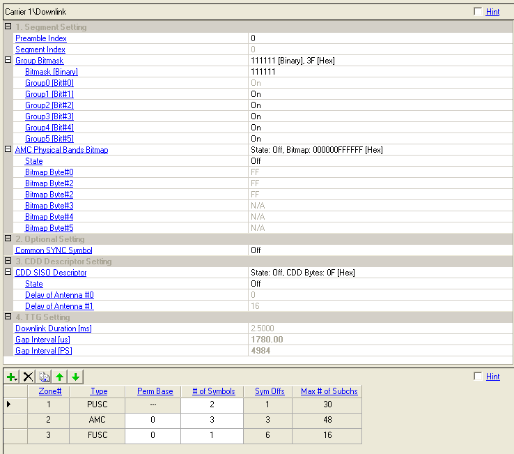
to display the downlink configuration node. This view displays the downlink
settings in the top half and buttons for adding up to 8 zones (PUSC, FUSC,
or AMC) in the bottom half. This software supports AMC 2x3 zones.
 Click in the  tree view
to display the downlink configuration node. This view displays the downlink
settings in the top half and buttons for adding up to 8 zones (PUSC, FUSC,
or AMC) in the bottom half. This software supports AMC 2x3 zones.

Range: 0 to 113
Set the preamble index number.
The preamble index value determines the ID Cell and segment index values according to Table 309 in the standard.
Range: 0 to 2
Displays the segment index that is associated with the selected preamble index as specified in Table 309 in the standard. The selected segment index results in the following settings for the Group Bitmask:
0 = Group0 (Bit#0) is always On
1 = Group2 (Bit#2) is always On
2 = Group4 (Bit#4) is always On
When FFT Size is 512, Bit # 1, 3, 5 are not available.
Range: 000000 to 111111 [Binary], 00 to 3F [Hex]
Click  to expand this cell to select which groups of subchannels are
assigned to the segment.
Enter a 6-bit binary number in the Bitmask [Binary] cell using 1 for
assigned groups and 0 for unassigned groups, or choose On or Off in the
corresponding cells for each group. (The software automatically sets  one bit
that cannot be edited corresponding to the segment index.)
The value of 111111 [Binary] or 3F [Hex] assigns all  available subchannels
in each group based on the selected FFT size.
The Group Bitmask value affects Max. Number of Subchannels when Use All Subchannels is Off. In that case the Zone Boost Factor is also calculated from the bitmask.
Although the software allows you to configure only one segment, you may want to turn off some of the groups to simulate the situation where other segments are in use.
Range: 0x000000000000 to 0xffffffffffff
Set the downlink physical bands bitmap of the AMC Zone.
Choice: On, Off
Double-click or use the drop-down menu to set the state of the AMC Physical Bands Bitmap.
Range: 0x00 to 0xff [Hex]
Set the uplink bitmap byte.
Double-click or use the drop-down menu to turn the On or Off. The common SYNC symbol length is one symbol.
On - The last OFDM symbol is used for the common SYNC symbol in every fourth downlink transmission frame. If the built frames range does not include any frames that are multiples of four, a caution message is displayed in the parameter status window.
Off - The Common Sync Symbol is not used.
The Common Sync Symbol is not transmitted when FFT = 2048.
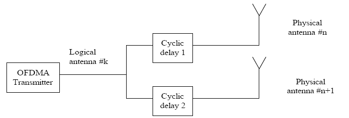
The BS and MS may apply the cyclic delay diversity (CDD) technique in order to improve performance or split the power between multiple transmit antennas. The same signal (including data, pilots, preamble, midamble, etc) may be transmitted from several antennas simultaneously, with different cyclic delay applied to each signal in order to reduce the potential of nulling in the receiver's antenna. Cyclic delay means the samples in the useful symbol time Tb are shifted D samples forward, the last D samples are copied to the first D samples, and the CP is regenerated from the last samples of the rotated symbol. An equivalent description is to multiply all subcarriers by Wk=exp(-j2πDk/N). Each transmit antenna uses a different delay value and potentially a different gain and phase.

Figure Example of single logical antenna split into two physical antennas with cyclic delays
Choice: On, Off
Double-click or use the drop-down menu to control the operating state of CDD Descriptor.
Range: 1 to 32
Set CDD delay of tap 0 on antenna #0 in the CDD Descriptor Setting
Range: 1 to 32
Set CDD delay of tap 0 on antenna #1 in the CDD Descriptor Setting
Displays the downlink duration in milliseconds, taken from the Waveform Setup node.
Displays the size of the TTG interval in microseconds.
The maximum gap size depends on the sampling rate, oversample ratio, cyclic prefix, and frame size. Editing the Gap Interval [samples] recalculates this value automatically.
Displays the size of the TTG interval in Physical Slots.
The maximum gap size depends on the sampling rate, oversample ratio, cyclic prefix, and frame size. Editing the Gap Interval [us] recalculates this value automatically.
1 PS = 4/Fs, per section 10.3.4.2 in P802.16Rev2/D6.
The following settings are only available When Output Mode is set to Downlink Only (FDD/H-FDD) or Uplink Only(FDD/H-FDD).
Displays the subframe duration in milliseconds.
Displays the size of the unused interval of downlink subframe in microseconds
Displays the size of the unused interval of downlink subframe in symbol units. You cannot edit this cell.
Use the button  to add a new downlink zone type to the frame configuration from the
  pull-down menu.
When a zone is added, the software inserts the zone (up to eight) in the
tree view with a default burst and MAC PDU and adds it to the frame plot view.
Use the button  to delete the selected zone. The zone to be deleted is indicated by the
 in the first column. The first PUSC zone cannot be deleted.
Use the button  to add a new zone that has the same configuration as the currently selected
one (indicated by the
  in the first column).
Use the and
arrows  to reposition the currently selected zone (indicated by the
 in the first column).
This cell displays the zone index number.
Choices: PUSC, FUSC, AMC
This cell displays the zone type. The zone type is selected from the
 pull-down menu.
PUSC = partial usage of subchannels
FUSC = full usage of subchannels
AMC = adaptive modulation and coding (AMC 2x3 zones are supported.)
Range: 0 to 31
Use this cell to select the permutation base to be used for subchannel randomization in the zone.
Refer to section 8.4.5.3.4, Space-Time Coding (STC)/DL Zone switch IE format, section 8.4.9.4, Modulation, and section 8.4.6, OFDMA subcarrier allocation in P802.16-2004/Cor1/D3 for standard specifications.
This parameter does not apply to the first PUSC zone.
Use this cell to specify the number of symbols in this zone.
This cell displays how much the zone is offset from the beginning of the downlink subframe. The symbol offset displayed includes the default preamble (1 symbol). See also Symbol Offset.
This cell displays the maximum number of subchannels per symbol for the zone configuration.