PUSC, Zones 2 through 8 have two additional parameters. These parameters are not present in Zone#1, PUSC. Other parameters are the same for all PUSC zones.
Use this cell to select the permutation base (0 to 31) to be used for subchannel randomization for all segments in the PUSC downlink zone as specified in section 8.4.5.3.4. Space-Time Coding (STC)/DL Zone switch IE format of P802.16-2004/Cor1/D3. Accepted values are 0 to 31.
This parameter does not apply to Zone#1, PUSC.
Use this cell to set the PRBS ID (0 to 2) in the zone to be used for subchannel randomization as specified in 8.4.5.3.4 Space-Time Coding (STC)/DL Zone switch IE format of P802.16-2004/Cor1/D3.
This parameter does not apply to Zone#1, PUSC.
Double-click or use the drop-down menu to turn Use All Subchannels On or Off.
On - all subchannels will be used for this zone.
Off - subchannels are assigned in the Group Bitmask.
This parameter is read-only for the first PUSC zone, and is always Off.
Double-click or use the drop-down menu to turn On or Off.
On - adds gain to the used subchannels.
Off - the average power of a zone is lower.
Zone Boost is not available when Use All Subchannels is On.
Displays the zone boost amplitude in dB when zone boosting is enabled.
This value is automatically calculated based on Group Bitmask for PUSC zone and AMC Physical Bands Bitmap for AMC zone. Refer to 8.3.9.6 in P802.16Rev2/D6 for details.
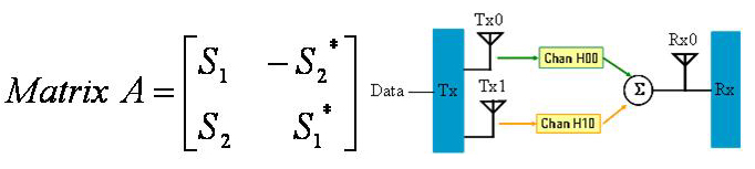
Double-click or use the drop-down menu to select the STC type, which decides whether this DL-PUSC zone implements Matrix A, Matrix B or None STC encoding. For the first DL-PUSC zone, it should always be None.
: Apply SISO signal effect for single antenna setup
: Also
known as Space-Time Code (STC). Transmit diversity is supported to provide
spatial diversity and reduce fading margin. For STC, the number of transmitter
antennas is 2 and the number of receiver antennas is equal to or greater
than 1.  View illustration.
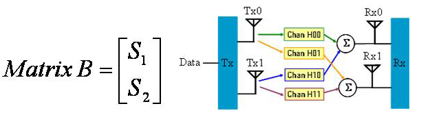
: Also
known as Spatial Multiplexing (SM) or MIMO. Multiple streams are transmitted
over multiple antennas to achieve higher throughput. For MIMO, the number
of transmitter antennas is equal to 2. The number of the receiver antennas
is equal to or larger than 2. View illustration.
Double-click or use the drop-down menu to select the MIMO DL IE Format.
: All the bursts are described in one single MIMO DL IE.
: Each burst is described in one separate MIMO DL IE.
: The bursts whose STC Type is the same with that of the zone are described in Normal burst IEs, while all the other bursts are described in one single MIMO DL IE.
: The bursts whose STC Type is the same with that of the zone are described in Normal burst IEs, while each of the other bursts are described in separate MIMO DL IEs.
MIMO DL IE Format is only available in STC mode.
Choices: On, Off
Use the drop-down menu or double-click to turn Dedicated Pilots on or off.
Dedicated Pilots On - use dedicated pilots transmission in the non-first DL-PUSC zone.
Dedicated Pilots Off - use full pilots transmission in the non-first DL-PUSC zone.
Specify the number of symbols in this zone.
The value must be an even number because DL PUSC is divided into slots
of 2 symbols x 1 subchannel (section 8.4.3.1 in 802.16-2004/Cor/D3). See
example.
Displays the symbol offset from the beginning of the downlink subframe.
The symbol offset displayed includes the default preamble (1 symbol).
Displays the maximum number of subchannels per symbol for the zone configuration.
If is On, it depends on the FFT size only.
If is Off, it depends on the FFT size and the subchannel allocation as set in Group Bitmask.
Double-click or use the pull-down menu to turn this feature on or off.
On - automatically configure all of the burst allocations in this zone to help avoid burst overlap.
Off - the burst allocations for , , , and are configurable.