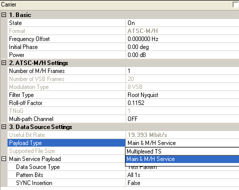
ATSC-M/H (Advanced Television Systems Committee - Mobile/Handheld) is an extension to the ATSC standard for the delivery of real-time and non-real-time television content and data to mobile and handheld receivers. For a detailed introduction of the ASTC-M/H transmission system, refer to ATSC-M/H Transmission System Introduction.

Click on the link of each parameter for details.
Double-click or use the drop-down menu to control the operating state of the carrier.
The format of the carrier.
Range: -50.0 to 50.0 MHz
Set the frequency offset for the carrier relative to the signal generator’s center frequency.
The valid range will be different for every format with various over-sampling ratio.
Range: 0 to 359 degrees
Set the initial phase of the carrier.
Range: -50 to 0 dB
Sets the power level in dB for the selected carrier in a multiple carrier configuration, relative to the power settings defined for the other carriers in the configuration.
You can ignore this parameter for single carrier configurations. In single carrier configurations, the amplitude of the signal is determined by the Amplitude setting in the Instrument node.
Range: 1 to 250
Default: 1
Set the number of ATSC-M/H frames. One M/H frame consists of 20 VSB frames.
To learn more about the M/H Frame structure, refer to ATSC-M/H Frame Structure.
Range: 1: 5000
Default: 20
This cell shows the number of VSB frames. Each M/H frame contains 20 VSB frames.
View the modulation type, 8VSB.
Choice: Root Nyquist | Nyquist
Default: Root Nyquist
Double-click or use the drop-down menu to select the filter type for the ATSC-M/H signal.
Range: 0 to 1
Default: 0.1152
Set the roll-off factor for the ATSC-M/H signal.
Range: 1 to 16
Default: 1
View the total number of groups per M/H sub-frame under current settings.
Default: OFF
To
enable static multi-path channel, click on in the right side of the cell, the
![]() Multi-path
Channel configuration
window
Multi-path
Channel configuration
window
will pop up.
View the useful bit rate, which can be transmitted by current encoding, modulation, and framing configurations.
Choice: Main & M/H Service | Multiplexed TS
Default: Main & M/H Service
Double-click or use the drop-down menu to select the payload type for ATSC M/H.
The two types of payloads correspond to two
input points in the ![]() ATSC-M/H transmission system:
Point A and Point B.
ATSC-M/H transmission system:
Point A and Point B.
Main & M/H
Service: If this payload type is selected, the input payloads should be
the main service payload and the M/H service payload at point A. Then
you need to configure both the Main Service Payload under the ![]() Carrier node
and the M/H Service Payload for each parade under the
Carrier node
and the M/H Service Payload for each parade under the ![]() Parade node.
Parade node.
Multiplexed TS: If this payload type is selected, the input payload should be the service data after packet multiplexer at point B, including both the M/H service data and main service data. In this case, the software will decode the TPC (Transmission Parameter Channel) information from the input multiplexed TS and then couple to the settings for each parades automatically. All the settings under Parade node will be grayed out.
View the supported file size for the current settings.
Choice: Test Pattern | Demo File | TS File | TS File Wizard
Default: Test Pattern
Double-click or use the drop-down menu to select which type to be used as the main service payload.
If "TS File" is selected, "File Name" is required; If "TS File Wizard" is selected, "File Wizard" is available.
To learn more about the different Data Source Types, refer to the page Data Source Type.
Set the data bits used as test pattern.
Click
the in the right side of the cell to open "Data
Pattern Selection" dialog and select the test pattern to use.
Choice: True | False
Default: False
Double-click or use the drop-down menu to determine whether or not the SYNC byte (0x47) will be inserted into the test pattern.
Click the
in the right side of the cell to browse the computer and select a multiplexed
TS file for the ATSC-M/H signal.
If a multiplexed TS file is selected, the software will decode the TPC (Transmission Parameter Channel) information, which includes the parameters for the M/H frame and each parade, from the input multiplexed TS and then couple the parameters to the settings for each parades automatically. Thus, all the settings under Parade node will be grayed out.