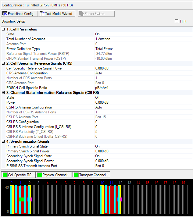
Click the Predefined Configuration button to access
a ![]() dialog box
from which you can select a base channel configuration.
dialog box
from which you can select a base channel configuration.

The Test Model Wizard button opens a window from which you can select a test model type and set or view other related parameters. In the ETM test Mode, it will generate with two different frame settings.

Click the ETM Two Frames Switch button to see the settings for different frames.
Links to parameter descriptions are listed in the tables below.
|
2. Cell Specific Reference Signal |
|
|---|---|
| Total Number of Antennas | CRS Antenna Configuration |
| Number of CRS Antenna Ports | |
| PDSCH Cell Specific Ratio | |
|
|
|
3. Channel State Information Reference Signals (CSI-RS) |
4. Synchronization Signals |
|---|---|
|
|
|
|
|
|
|
|
Choice: On | Off
Default: On
Double-click or use the drop-down menu to turn the downlink transmission off or on.
Choice: 1 Antenna | 2 Antennas | 4 Antennas | 8 Antennas
Default: 1 Antenna
In multi-antenna configurations, specify the total number of physical antenna port configurations to be used for downlink transmission for this cell. The combination of the Total number of Antennas and Number of CRS Antenna Ports determines the resource elements that are reserved for the Cell-specific reference signals as described in 3GPP TS 36.211.
For multiple signal generator configurations, set the Channel State parameter in the Fading section of the Carrier node to On to make this cell active. When the channel state is off, you must change the number of signal generators (for example, Quick Setup M x 1, M x 2, M x 4) to change the number of BS antennas.
MIMO pre-coding is not applied in the Basic carrier. Use an Advanced carrier for generating a signal with MIMO pre-coding applied.
Choice: 0 | 1 | 2 | 3 | 4 | 5 | 6 | 7
Default: 0
In multi-antenna configurations, specify the physical antenna port used for transmitting the downlink signal. The available selections depend on the total number of antennas selected. The number of Antenna Ports should be equal to or less than the Total Number of Antenna Ports.
With a Basic carrier, only one antenna port is available for signal transmission. The combination of the Antenna Port setting and the Total number of Antennas setting determines the resource elements that are reserved for reference signals as described in 3GPP TS 36.211.
MIMO pre-coding is not applied in the Basic carrier, use an Advanced carrier for generating a signal with MIMO pre-coding applied.
Choice: Total Power | RSTP
Default: Total Power
Double-click or use the drop-down menu to select the power definition type for the primary cell.
The power definition type for secondary cells is automatically set same type of the primary cell and set the value as read-only.
In multiple carrier case, Power Definition Type parameter in each carrier should be same.
If Total Power is selected, power reference is Amplitude parameter on Instrument node. In single/multiple carrier and Total Power case, RSTP and OSTP are automatically calculated by Amplitude parameter on Instrument node, Power parameter on Component Carrier and each carrier signal settings.
If RSTP is selected, power reference is RSTP. In single/multiple carrier and RSTP case, Amplitude parameter on Instrument node, Power parameter on Component Carrier and OSTP are automatically calculated by RSTP and each carrier signal settings. In this case, Power parameter on Component Carrier is set read-only.
If uplink and downlink carriers are mixed as multiple carrier, correct RSTP calculation is not available.
Range: -15.00 to -144.00 dBm
Default: -40.79 dBm
Enter the Reference Signal Transmit Power in dBm, when the Power Definition Type is RSTP. Otherwise displays the Reference Signal Transmit Power in dBm and the value is updated after generation.
In the case Power Definition Type is Total Power, RSTP is automatically calculated by Amplitude parameter in Instrument, Power parameter in Component Carrier and each carrier signal settings.
In the case Power Definition Type is RSTP, Amplitude parameter in Instrument and Power parameter in the Component Carrier is automatically calculated and set the value as read-only.
Available setting range and step depends on hardware.
See 3GPP TS 36.141 for more information.
Display the Downlink OFDM Symbol Transmit Power in dBm.
For detailed information about OSTP, refer to the 3GPP TS 36.141 document at http://www.3gpp.org.
Cell specific reference signals are intended for all UEs within the cell.
Range: -60 to 20 dB
Default: 0 dB
Enter a power level in dB for the cell specific reference signal.
Choice: Auto | Manual
Default: Auto
Double-click or use the drop-down menu to select the CRS Antenna Configuration.
This parameter specifies both the Number of CRS Antenna Ports and the CRS Antenna Port setting. The possible settings are either Auto (automatically set by the software) or Manual (you can set them).
Choice: Auto | 1 | 2 | 4
Default: Auto
Double-click or use the drop-down menu to select the number of antennas for cell specific reference signals (CRS). The combination of the number of CRS antenna ports setting and the total number of antennas determines the resource elements that are reserved for reference signals as described in 3GPP TS 36.211.
If CRS Antenna Configuration is set to Auto, the software sets the number of CRS Antenna Ports equal to or less than the Total Number of Antennas.
Examples (where: CRS Antenna Configuration = Auto):
Total Number of Antennas = 4, then the Number of CRS Antenna Ports = 4
Total Number of Antennas = 8, then the Number of CRS Antenna Ports = 4
If CRS Antenna Configuration is set to Auto, the software sets the Number of CRS Antenna Ports the same as the Total Number of Antennas.
Choice: Port 0 | Port 1 | Port 2 | Port 3
Default: Port 0
Double-click or use the drop-down menu to select the antenna port to use for CRS transmission. Available port selections depend on the number of CRS antenna ports selected.
If CRS Antenna Configuration is set to Auto, CRS Antenna Port is set same as ((Antenna Port) mod (Number of CRS Antenna Ports)).
|
Total Number of Antennas |
Antenna Port |
Number of CRS Antenna Ports |
CSI-RS Antenna Configuration |
CRS Antenna Port |
|---|---|---|---|---|
|
1 Antenna |
Port 0 |
1 |
Manual |
Port 0 |
|
2 Antennas |
Port 0, 1 |
1 |
Manual |
Port 0 |
|
|
|
2 |
Manual |
Port 0, 1 |
|
4 Antennas |
Port 0, 1, 2, 3 |
1 |
Manual |
Port 0 |
|
|
|
2 |
Manual |
Port 0,1 |
|
|
|
4 |
Manual |
Port 0, 1, 2, 3 |
|
|
|
|
Auto |
Same as: (Antenna Port) mod (Number of CRS Antenna Ports) |
Refer to 3GPP TS 36.211.
Choice: pB/pA=1 | P_B=0 | P_B=1 | P_B=2 | P_B=3
Default: pB/pA=1
Double-click or use the drop-down menu to select the PDSCH cell specific ratio.
Choice: On | Off
Default: On
Double-click or use the drop-down menu to turn the channel state on or off. See Output Power Calculation (Downlink) for a description of how the software applies your power settings.
Range: -60.000 to 20.000 dB
Default: 0.000 dB
Enter a power level in dB for the channel state information reference signal.
Choice: Auto | Manual
Default: Auto
Double-click or use the drop-down menu to select the CSI-RS Antenna Configuration.
This parameter indicates both the parameter settings for both the Number of CSI-RS Antenna Ports and the CSI-RS Antenna Port parameters. The possible settings are either Auto (automatically set by the software) or Manual (you can set them).
Choice: 1 | 2 | 4 | 8
Default: 1
Double-click or use the drop-down menu to select the number of antenna ports for CSI-RS signals less than or equal to the total number of antennas.
The combination of the number of CSI-RS antenna ports and the total number of antennas determines the resource elements that are reserved for reference signals as described in 3GPP TS36.211.
If Auto is selected, the software sets the number of CSI-RS antenna ports equal to the total number of ports.
Choice: Port 15 | Port 16 | Port 17 | Port 18
Default: Port 15
Double-click or use the drop-down menu to select the antenna port for CSI-RS transmission. Available port selections depend on the number of CSI-RS antenna ports selected. For more detail, refer to 3GPP TS 36.211.
|
Total Number of Antennas |
Antenna Port |
Number of CSI-RS Antenna Ports |
CSI-RS Antenna Configuration |
CSI-RS Antenna Port |
|---|---|---|---|---|
|
1 |
Port 0 |
1 |
Manual |
Port 15 |
|
2 |
Port 0, 1 |
2 |
Manual |
Port 15, 16 |
|
4 |
Port 0, 1, 2, 3 |
4 |
Manual |
Port 15, 16, 17, 18 |
|
|
|
8 |
Manual |
Port 15, 16, 17, 18, 19, 20, 21, 22 |
|
|
|
|
Auto |
Antenna port + 15 |
Range: 0 to 31
Default 0
Enter the CSI-RS subframe configuration index for the CSI-RS. This defines both the CSI -RS periodicity and subframe offset in accordance with 3GPP TS 36.211.
The CSI-RS Configuration range is coupled to the Number of CSI-RS Antenna Ports and to the Cyclic Prefix.
The available range depends on the following settings:
|
Normal Cyclic Prefix |
Extended Cyclic Prefix |
Number of CSI-RS |
|---|---|---|
|
0 - 31 |
0 - 27 |
1 or 2 |
|
0 - 9, 20-25 |
0 - 7, 16-21 |
4 |
|
0 - 4, 20-22 |
0 - 3, 16-18 |
8 |
Range: 0 to 74
Default: 0
Enter the CSI-RS Subframe Configuration Index which defines both the CSI-RS Periodicity (T_CSI-RS) and the CSI-RS Subframe Offset (Delta_CSI-RS).
|
CSI -RS Subframe Configuration |
CSI-RS periodicity (subframes) |
CSI_RS subframe offset |
|---|---|---|
|
0 - 4 |
5 |
CSI-RS |
|
5 - 14 |
10 |
CSI-RS - 5 |
|
15 -34 |
20 |
CSI-RS - 15 |
|
35 - 74 |
40 |
CSI-RS - 35 |
This is read only parameter automatically set by the CSI-RS Subframe Configuration (I_CSI-RS). For more detail, refer to 3GPP TS 36.211.
Subframes containing CSI reference signals shall satisfy (10*SFN + Floor(Slot#/2) - Delta_CSI-RS) mod T_CSI-RS = 0
I_CSI-RS = 0 to 4 , T_CSI-RS = 5
I_CSI-RS = 5 to 14, T_CSI-RS = 10
I_CSI-RS = 15 to 34, T_CSI-RS = 20
I_CSI-RS = 35 to 74, T_CSI-RS = 40
This is read only parameter automatically set by the CSI-RS Subframe Configuration (I_CSI-RS). For more detail, refer to 3GPP TS 36.211.
This is coupled to CSI-RS Subframe Configuration (I_CSI-RS).
Subframes containing CSI reference signals shall satisfy (10*SFN + Floor(Slot#/2) - Delta_CSI-RS) mod T_CSI-RS = 0
I_CSI-RS = 0 to 4 , Delta_CSI-RS = I_CSI-RS
I_CSI-RS = 5 to 14, Delta_CSI-RS = I_CSI-RS - 5
I_CSI-RS = 15 to 34, Delta_CSI-RS = I_CSI-RS - 15
I_CSI-RS = 35 to 74, Delta_CSI-RS = I_CSI-RS - 35
Choice: Off | On
Default: On
Double-click or use the drop-down menu to turn the primary synchronization signal (P-SS) On or Off.
Range: -60 to 20 dB
Default: 0 dB
Enter the power level in dB for the primary synchronization signal.
Choice: Off | On
Default: On
Double-click or use the drop-down menu to turn the secondary synchronization signal (S-SS) On or Off.
Range: -60 to 20 dB
Default: 0 dB
Enter the power level in dB for the secondary synchronization signal.
Choice: Port 0 | Port 1 | Port 2 | Port 3 | All Ports
Default: Port 0
Double-click or use the drop-down menu to select the P-SS/S-SS Transmit Antenna Port type.