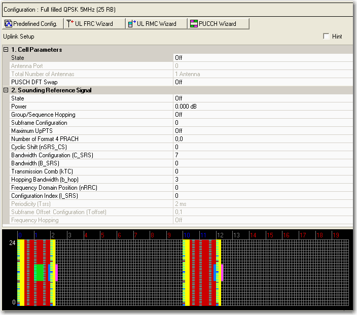

Click the Predefined Configuration button to access a dialog box from which you can select a base channel configuration.
To use a Wizard to configure your channels:

Click the Wizard button to open the UL FRC Wizard to set up a UL fixed reference channel (FRC).
Click the Wizard button to open the UL RMC Wizard to set up a UL reference measurement channel (RMC) for transmitter performance.
Click the Wizard button to open the PUCCH Wizard to set up a multi-user PUCCH test.
Click the links in the table below the graphic for parameter descriptions.

|
2. Sounding Reference Signal |
|
|---|---|
|
|
|
|
|
|
|
|
|
|
|
|
|
|
|
|
|
|
|
|
|
|
|
|
|
|
|
|
|
|
|
|
Choice: Off | On
Default: Off
Double-click or use the drop-down menu to turn the uplink transmission off or on.
Displays the antenna port number.
Displays the total number of antennas.
Choice: Off | On
Default: Off
Double-click or use the drop-down menu to turn PUSCH DFT Swap on or off.
PUSCH DFT Swap influences how data is mapped to resource elements in the physical uplink shared channel after discrete Fourier transform is performed. PUSCH DFT Swap can be turned on or off to provide two different interpretations of how data should be mapped to resource elements in PUSCH channels.
Choice: Off | On
Default: Off
Double-click or use the drop-down menu to turn the sounding reference signal on or off.
Range: -60.000 to 20.000 dB
Default: 0.000 dB
Set the power of the sounding reference signal in dB.
Choice: Off | Group Hopping | Sequence Hopping
Default: Off
Double-click or use the drop-down menu to select the hopping type sounding reference signal related to. (See 3GPP TS 36.211)
Choice: 0 | 1 | 2 | 3 | 4 | 5 | 6 | 7 | 8 | 9 | 10 | 11 | 12 | 13
Default: 0
Double-click or use the drop-down menu to select subframe configuration of sounding reference signal.
Choice: Off | On
Default: Off
Double-click or use the drop-down menu to turn the sounding reference signal Max UpPTS state on or off.
Set the Number of Format 4 PRACH burst allocated in the special subframe, you can set this value to 0, 1, 2, 3, 4 ,5, 6 for each special subframe as described in 3GPP TS 36.211.
Choice: 0 | 1 | 2 | 3 | 4 | 5 | 6 | 7
Default: 0
Double-click or use the drop-down menu to select the value which is used to calculate the cyclic shift for sounding reference signal.
Choice: 0 | 1 | 2 | 3 | 4 | 5 | 6 | 7
Default: 7
Double-click or use the drop-down menu to select the Bandwidth configuration for sounding reference signal.
Choice: 0 | 1 | 2 | 3
Default: 0
Double-click or use the drop-down menu to select the Bandwidth indicator for sounding reference signal.
SRS Bandwidth (B_SRS), SRS Hopping Bandwidth (b_hop), and Frequency Hopping are related as follows:
Frequency Hopping On: SRS Hopping Bandwidth (b_hop) < SRS Bandwidth (B_SRS)
Frequency Hopping Off: SRS Hopping Bandwidth (b_hop) >= SRS Bandwidth (B_SRS)
Choice: 0 | 1
Default: 0
Double-click or use the drop-down menu to select the offset value which is related with the transmission comb for sounding reference signal.
Range: Choice: 0 | 1 | 2 | 3
Default: 3
Double-click or use the drop-down menu to select the frequency hopping bandwidth of sounding reference signal.
SRS Bandwidth (B_SRS), SRS Hopping Bandwidth (b_hop), and Frequency Hopping are related as follows:
Frequency Hopping On: SRS Hopping Bandwidth (b_hop) < SRS Bandwidth (B_SRS)
Frequency Hopping Off: SRS Hopping Bandwidth (b_hop) >= SRS Bandwidth (B_SRS)
Range: 0 to 23
Default: 0
Enter the frequency domain position RRC value which is from the upper layer for sounding reference signal.
Choice: 0 to 644
Default: 0
Enter the configuration Index for sounding reference signal.
SRS Bandwidth (B_SRS), SRS Hopping Bandwidth (b_hop), and Frequency Hopping are related as follows:
Frequency Hopping On: SRS Hopping Bandwidth (b_hop) < SRS Bandwidth (B_SRS)
Frequency Hopping Off: SRS Hopping Bandwidth (b_hop) >= SRS Bandwidth (B_SRS)
This is read only parameter and the value is automatically selected by the software. Refer 36.213V8.5.0 Table 8.2-1
This is read only parameter and the value is automatically selected by the software. Refer 36.213V8.5.0 Table 8.2-1
This is read only parameter and the value is automatically selected by the software.
SRS Bandwidth (B_SRS), SRS Hopping Bandwidth (b_hop), and Frequency Hopping are related as follows:
Frequency Hopping On: SRS Hopping Bandwidth (b_hop) < SRS Bandwidth (B_SRS)
Frequency Hopping Off: SRS Hopping Bandwidth (b_hop) >= SRS Bandwidth (B_SRS)