Open topic with navigation
MIMO Characteristic Performance Analysis
Overview
The following characteristic performance results and analysis are for
typical 2X2 MIMO systems comprised of E4438C ESG, N5182A/N5182B MXG, and N5172B EXG
vector signal generators. They are valid for N7625C Signal Studio Pro for LTE/LTE-Advanced TDD 2026 and also for other Signal Studio applications that support MIMO
(for example, N7615C Signal Studio for 802.16 WiMAX
and N7617C Signal Studio for 802.11 WLAN) since this performance is determined
by the hardware platform and not the application-specific signals/waveforms.
This topic describes the MIMO performance for the following vector signal
generators:
E4438C ESG Performance
Test Overview
The following ESG MIMO configurations were tested:
A: ESGMIMO System without
Baseband Timing Alignment or RF Phase Coherence
B: ESGMIMO System with
Baseband Timing Alignment without RF Phase Coherence
C: ESGMIMO System with
Baseband Timing Alignment and RF Phase Coherence
Two characteristic performance attributes were analyzed for each configuration.
They are Phase Difference (between 2 ESG’s) vs.
Time (at a fixed temperature) and Phase Difference vs.
Temperature. The Keysight dual channel 89641S vector
signal analyzer (VXI) was used to perform the measurements.
The phase difference and other noise introduced by the 89641S have been
removed from the measurement results, so the signal generator performance
is accurately represented.
The following characteristic performance graphs are representative of
the measurement results achieved on three sets of 2-ESG systems.
Test Results
Legend for pictures below:
-
Dark blue curve
- measured phase difference.
-
Light blue curve
- mean value of phase difference (every 20 points).
-
Pink line - Fitted
line from the dark blue curve; shows the trend of the phase difference.
|
1. Results of configuration A: Two ESG MIMO system without common baseband clock and without
RF phase coherency
|

Figure 1-1 Phase difference over time
for configuration A
At fixed room temperature of 26° C; Output Power = –10
dBm; Frequency = 2.412 GHz.
240 test points per 60 minutes.
From the plot, we can see 2.8 degrees phase change over 12 hours (pink
line). The average peak-to-peak jitter of the phase difference is about
1.5 degrees (dark blue curve).
|

Figure 1-2
Phase difference over temperature for configuration A
Output Power = –10
dBm; Frequency = 2.412 GHz
From the plot, we can see about 35 degrees
phase change per degree Celsius temperature change.
|
|
2. Results of configuration B: Two ESG MIMO system with common baseband clock and without
RF phase coherency
|
|

Figure 2-1 Phase difference over time
for configuration B
At fixed room temperature of 26° C; Output Power = –10
dBm; Frequency = 2.412 GHz.
240 test points per 60 minutes.
From the plot, we can see 5.8 degrees phase change over 12 hours. The
average peak-to-peak jitter of the phase difference is about 1.5 degrees.
|

Figure 2-2 Phase difference
over temperature for configuration B
Output Power = –10
dBm; Frequency = 2.412 GHz
From the plot, we can see about 40 degrees
phase change per degree Celsius temperature change.
|
|
|
|
3. Results of configuration C: Two ESG MIMO system with common baseband clock and with RF
phase coherency
|
|

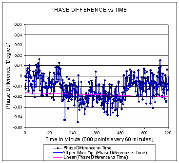
Figure 3-1 Phase difference over time for
configuration C
At fixed room temperature of 26° C; Output Power = –10
dBm; Frequency = 2.412 GHz.
240 test points per 60 minutes.
From the plot, we can see 0.17 degree phase change over 12 hours (pink
line). The average peak to peak jitter of phase difference is about 0.15
degree (dark blue curve).
|

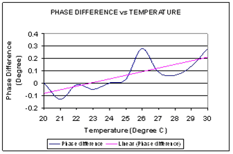
Figure 3-2 Phase difference
over temperature for configuration C
Output Power = –10
dBm; Frequency = 2.412 GHz
From the plot,
we can see about 0.03 degree phase change per degree Celsius temperature
change.
|
Analysis for ESG Performance
As seen in the phase difference drift measurement results above, there
are 2 main components in the phase difference drift:
1. Phase Difference A (referred to as PDA
in this document) is the jitter or noise-like vibration shown in the phase
difference curve, which is caused by phase noise.
2. Phase Difference B (referred to as PDB
in this document) is the trend of the phase difference drift.
We use "Phase Difference” as the simplification of "Phase
Difference Drift” in this document.
From the tests for all three cases, we can see that PDA dominates the
measurement results. PDB is much smaller and its impact
to most MIMO measurements is negligible. The analysis is:
-
If the environment temperature is stable (fixed), we
can see that the phase difference drift is very slow, so only in a long-term
continuous test could PDB be accumulated up to a value
to be comparable with PDA. The continuous test means that there is no
re-referencing in the test, i.e. no reset of the reference constellation
etc. If the test is not continuous, PDB will be eliminated
at re-referencing and will not be accumulated. Use configuration B, which
has the fastest phase difference drift, as an example: it takes about
(1.5/RMS_Factor )/(5.8/12) = 1.1 hour for PDB
to be accumulated up to be comparable with PDA (1.5 degree peak-to-peak
jitter) in a continuous test, where RMS_Factor is the
factor to convert peak phase difference to RMS phase difference. This
factor is 2.8, which is calculated from the test results. For configuration
A and C, which have slower phase difference drifts, it takes even longer
time.
-
If the environment temperature changes, the phase of
one source may change relative to another source, even when both are locked
to the same 10 MHz reference. The phase drift will
continue over a long period as the source stabilizes at the new temperature.
For example, if the environment temperature changes
5 degrees in 1 minute, it takes approximately 50 minutes for the source
phase to settle.
-
But in ordinary measurements, such as the EVM measurement
by the Keysight 89641S VSA, the data was captured within
periods of several hundred milliseconds. The test
reference (reference constellations) are reset at each capture (not continuous
across captures). So, according the analysis above, the PDB
doesn’t have time to accumulate in ordinary test (capture) periods
and therefore it is very small in ordinary measurements. Thus
it doesn't have any impact to the ordinary EVM and other MIMO measurements
as compared to PDA under either the fixed or changing temperature conditions.
In conclusion, PDA is the main factor that may impact your MIMO measurements,
and PDB can be ignored.
Worst-case equivalent EVM for the phase difference
values
If it is difficult for you to evaluate
the impact of the phase difference value to your MIMO measurements, here
we provide an approximate EVM equivalent to it which may help your evaluation.
But the following conditions must be noted:
-
The
values are worst case RMS EVM for the 2X2 MIMO setup with no fading case
and an assumption is that there is no correction or optimization capability
in the EVM measurement algorithm or the receiver. (Typically, either the
receiver or the EVM calculation will do optimization to get the smallest
residual EVM values.) Due to the pre-conditions above, the equivalent
EVM values are the worst case values and may not be seen in real measurements.
-
The phase difference needs
to be very small (<= 5 degrees) in order for us to take the approximations
below. For all of the test results above, this assumption is met.
As concluded above, only PDA needs to be
considered when making EVM measurements. As a result, the average peak-to-peak
magnitude values of jitter are used for the phase difference values.
According to the first condition above
(MIMO setup without fading, no correction), we can see the phase difference
is an error angle in the constellation, which will introduce an EVM phase
error without magnitude error. According to the second condition above,
the EVM value can be approximated by the sine or tangent value of the
phase difference, and then approximated to the phase difference itself
(in radians). So we get the following formula:
EVMrms
(worst-case equivalent) = (PhaseDifferencepp(peak-to-peak-of-jitter)
* PI/180) / (2*RMS_Factor)
where the factor 2 is the average factor
for a 2x2 MIMO system which is used to put the EVM into two spatial streams
to get the average EVM. RMS_Factor is the factor to
convert peak phase difference to RMS phase difference. This factor is
2.8, which is calculated from the test results.
So we get
EVMrms = 0.0031167* PhaseDifferencepp
This formula calculates the worst-case
equivalent EVM for the phase difference impact to your MIMO measurement
as below:
Conclusion
If your test requires phase coherency in
your MIMO systems (e.g. you are working on beamforming in MIMO), you should
choose configuration C.
Another benefit of configuration C is much
smaller PDA, which results in much smaller worst case equivalent EVM.
If you need to do high precision MIMO test, e.g. EVM with < 0.047%
precision, etc., you may choose configuration C. But be aware that other
components in your test setup, such as the receiver or analyzer, also
contribute noise error that impacts the final precision
of the measurements.
We don’t see significant differences
between configuration B and configuration A in terms of phase difference
drift. But configuration B will provide phase lock of the baseband clock
between the ESGs. So, you should choose it if you need the locked phase
(same phase or constant difference in phase) between the baseband clocks
of the 2 or more ESGs.
N5182A MXG, N5182B MXG, and N5172B EXG Performance
You can use multiple N5182A signal generators in the same system, or you can use N5172B and N5182B signal generators in the same system. However, you cannot use a mixture of N5182A signal generators and N5172B or N5182B signal generators in the same system.
If you are using an N5172B or N5182B and one or more N5182A signal generators, you must configure the N5172B or N5182B as the Master. In addition, the N5182A slaves must be at the end of the instrument chain.
Test Overview
The following MXG/EXG MIMO configurations were tested:
A: MXG/EXG
MIMO system with baseband timing alignment and without RF phase coherency
B: MXG/EXG
MIMO system with baseband timing alignment and with RF phase coherency
Two characteristic performance attributes were analyzed. They are Phase
Difference (between 2 MXG/EXG’s) vs.
Time (at fixed temperature) and Phase Difference vs.
Temperature. The Keysight dual channel 89641S vector signal analyzer (VXI)
was used to perform the measurements. The phase difference and other noise
introduced by the 89641S have been removed from the measurement results,
so the signal generator performance is accurately represented.
The following characteristic performance graphs are representative of
the measurement results achieved on two sets of 2-MXG/EXG systems.
Test Results
|
4. Results of configuration A: Two MXG/EXG MIMO
system with baseband timing alignment and without RF phase coherency.
|

Figure 4-1 Phase difference over time for
configuration A
At fixed room temperature of 25° C; Output Power = –10
dBm; Frequency = 2.412 GHz.
1 test point per minute.
From the plot, we can see the fastest trend change is 0.13 degrees Celsius
per minute. The average peak-to-peak jitter of phase difference is about
1.5 degrees.
|

Figure 4-2 Phase
difference over temperature for configuration A
Output Power
= –10 dBm; Frequency
= 2.412 GHz
From the plot,
we can see about 37 degrees phase change per degree Celsius temperature
change.
|
|
|
|
|
5. Results of configuration B: Two MXG/EXG MIMO
system with baseband timing alignment and with RF phase coherency.
|
|

Figure 5-1 Phase difference over time for
configuration B
At fixed room temperature of
26° C; Output Power = –10
dBm; Frequency = 2.5 GHz.
600 test points per 60 minutes.
From the plot, we can see a 0.05
degree phase change over 12 hours (pink line).
The average peak-to-peak jitter of phase difference is about 0.06 degrees
(dark blue curve).
|

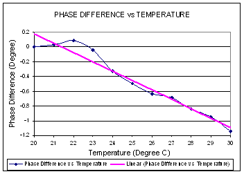
Figure 5-2 Phase difference
over temperature for configuration B
Output Power
= –10 dBm; Frequency
= 2.412 GHz
From the plot,
we can see about 37 degrees phase change per degree Celsius temperature.
|


