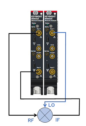
Internal Second Source PXI/USB setup is required.
Connect the RF input to port 1.
Connect the IF output to ports 2.
Connect the LO to port 3.
Ch1: Sweep input frequency and at output, measure LO fundamental and harmonic powers, plus spurs (in dBc relative to the input power), of order n*RF - m*LO, where n and m are integers 1, 2, and 3.
On the VNA front panel, press Meas > S-Param > Meas Class....
Select Differential I/Q, then either:
OK delete the existing measurement, or
New Channel to create the measurement in a new channel.
A Differential I/Q measurement is displayed.
Channel 1 will have 13 frequency ranges.
Click Stimulus, then DIQ Setup...
Click New 12 times for a total of 13 ranges.
Click Edit in each range, then enter the following:
F1 (RF Input): 3.0 GHz to 3.2 GHz; IFBW 1 kHz; Uncheck Couple
F2 (LO): 2.9 GHz to 2.9 GHz (CW); IFBW 1 kHz; Uncheck Couple.
F3 (2*LO): IFBW 1 kHz; Check Couple; Couple to: F2; Offset: F2; Multiplier: 2. Check UP.
F4 (3*LO): IFBW 1 kHz; Check Couple; Couple to: F2; Offset: F2; Multiplier: 3. Check UP.
F5 (1RF - LO); IFBW 1 kHz; Check Couple; Couple to: F1; Offset: F2; Uncheck UP.
Complete the remaining ranges (F6 to F13) using the above pattern and following formulas:
|
Range |
Formula |
Results |
|
F6 |
2RF-1LO (2*F1-F2) |
 |
|
F7 |
3RF-1LO (3*F1-F2) |
|
|
F8 |
1RF-2LO (1*F1-F3) |
|
|
F9 |
2RF-2LO (2*F1-F3) |
|
|
F10 |
3RF-2LO (3*F1-F3) |
|
|
F11 |
1RF-3LO (1*F1-F4) |
|
|
F12 |
2RF-3LO (2*F1-F4) |
|
|
F13 |
3RF-3LO (3*F1-F4) |
This example does NOT use external sources.
Learn more about these settings.
Make the following Source settings:
This example does NOT use phase control.
For Port 2 and 4, on the Source Configuration dialog:
Check Match Correction ON.
Then apply Match Correction for all ranges.
"Off+Match" is annotated on the Source setting dialog, although this is NOT shown in the images above.
Note: Some of the parameters above are NOT displayed. These parameters can be used as diagnostic or troubleshooting parameters. For example, the “M_” terms are created when match correction is applied, but they are not usually displayed directly.
C:\Program Files\Keysight\Network Analyzer\DocumentsTemplate\Samples\Setups\DiffIQ\Mixer_spurs.xml
For each parameter, click Stimulus, then Sweep, then X-axis Type...
Click Response, then Cal, then Cal All...
Select ports 1 through 3.