This topic describes how to perform an Installation Cal for standard systems which should be done each time a change is made to the configuration.
Installation Source Calibration
This process allows us to characterize the raw source power of each module by varying the power to the module and measuring the response over frequency using the reference receiver.
During this process we create a 2-D power table that would be used when we want to set the power at the port of the module.
User Source Power Calibration
This is only done prior to making a measurement that requires an accurate power at the measurement port, which could be the module test port or the end of a cable or adapter.
Generally is a single sweep measurement at the required power, and uses the Installation power calibration to adjust the power for different power levels.
IF Flatness calibration
For this process we require that the module do not have anything attached
In this case we adjust the IF loss from the receiver in the module to the IF input at the rear of the PNA-X
It also matches the IF to that of the internal DAC range.
Note: The Installation Cal must be performed before the Smart Cal procedure.
If power level control is required, perform Installation Calibration.
The Installation Calibration should be done each time a change is made to the physical configuration, i.e. a cable change, a change in millimeter head, or a PXI module change.
The Installation Calibration characterizes the input/output power relationship for each millimeter module.
The Installation Calibration results in a +/- 5 dB source power calibration.
The Installation Calibration does NOT provide any calibration of the VNA receivers.
The Installation Calibration is applied system wide. It can be enabled and disabled, but only on a system wide basis. It cannot be enabled or disabled on a channel by channel basis.
The following example is for a banded system. The sequence will be different for different port counts.

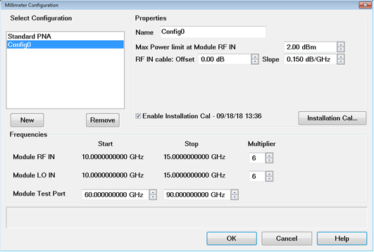
Click on OK to enable the configuration.
Press Setup > External Hardware > Millimeter Config to get back to the Millimeter Configuration Dialog.
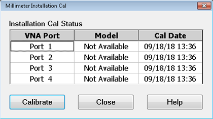
Click on the Installation Cal... button to launch the calibration. The following dialog is displayed. This dialog displays the calibration date for each port if calibration was previously performed. Otherwise, "Not Available" will be shown in the Cal Date column. Also, “Not Available” will be shown for the Model number, as the supported Frequency Extenders do not provide their Model numbers electronically.


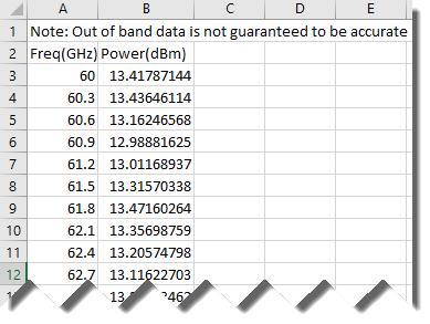
In the USB drive supplied with the millimeter wave module is a file containing maximum output power data. Open this file to find the maximum output power for the module and enter this value in the Enter Port 1 millimeter module's max output power field. It is important to enter the correct maximum power to get a good Installation Calibration. The following is an example of a section of this file.

Connect a waveguide load to Port 1.
Click the Measure button. The following dialog is displayed.

Follow the prompts to calibrate each port. Remember to enter the correct maximum power for each module.
When finished, the following dialog is displayed. Click the Finish button.

When finished, Enable Installation Cal in the Millimeter Configuration dialog should be checked and the calibration date/time displayed.
