Test fixture
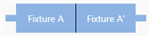
Thru standard
OR

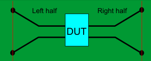
Left and Right halves of Thru standard


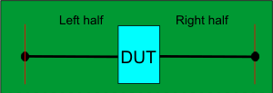
Supports both 1-port (not shown) and 2-port single-ended DUT configurations.
When used with a 4-port DUT configuration, the trace coupling is not removed.
Note: This feature requires Option S9x007A/B or 007.
In this topic:
Fixtures are often used for DUTs that have non-coaxial interfaces. This feature allows you to mathematically remove, or de-embed, a characterized test fixture from displayed measurement results of the test fixture and DUT.
Before starting the AFR process, Perform a calibration at the connectors of the test fixture (red lines in images below).
The AFR Wizard will guide you through these steps:
Press Cal > Fixtures > Auto Fixture Removal....
Describe your fixturing situation.
Specify How the Thru fixture characterization will occur.
Do characterization.
Remove the effects of the test fixture. Leaves ONLY the displayed results of the DUT.
Touchstone files are saved that characterize the two halves of the test fixture.
Test fixture and either a complete Thru OR Left and Right Thru halves, all shown below.
Both the Test fixture and Thru are made of the exact same medium; preferably fabricated ON the same piece of medium.
|
Test fixture |
|
|
Thru standard
OR |
|
|
Left and Right halves of Thru standard |
|
|
Supports both 1-port (not shown) and 2-port single-ended DUT configurations. When used with a 4-port DUT configuration, the trace coupling is not removed. |
|
|
Test fixture |
|
|
Thru standard
OR |
|
|
Left and Right halves of Thru standard |
|
|
Supports 4-port DUT configuration ONLY which includes removing the effects of coupling between the differential traces. |
|
With a calibrated measurement of the DUT in the test fixture present:
Click Response, then Cal, then Fixtures, then Automatic Fixture Removal
Note: The dialogs below show images for a Single ended DUT, but Differential works exactly the same, only with Differential S4P files.
|
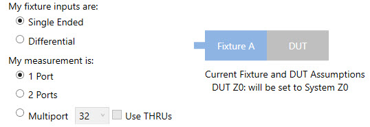
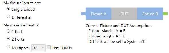
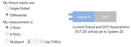
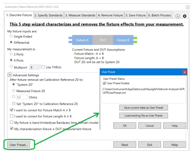
For best results, follow the AFR Wizard tabs from steps 1 through 5 by either clicking Next > or clicking the tabs. In this section: 1. Describe FixtureThe choices that you make in the dialog are reflected in the diagram and text (red box in following image). 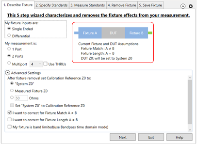
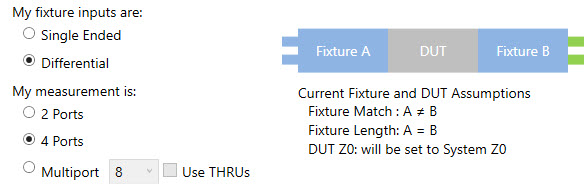
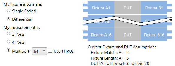
My fixture inputs are:
My measurement is (Single Ended):
My measurement is (Differential):
Advanced Settings (click ^ to show and hide)After fixture removal set Calibration Reference Z0 to: (Choose one of these settings)
Select all that apply:
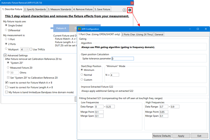
AFR Configuration DialogThe AFR Configuration dialog can be launched by clicking on the AFR Config icon (shown below).
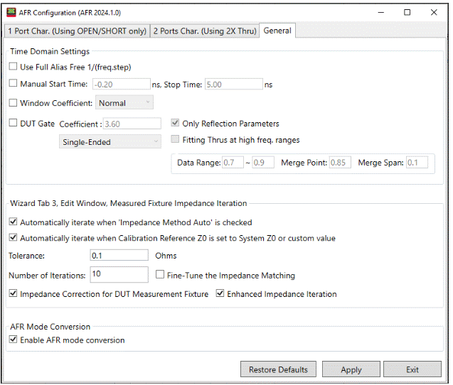
Access the following settings in the General tab of the AFR Configuration dialog.
Set manual time domain start and stop settings for corner cases shown under Time Domain Settings. Use Full Alias Free 1/(freq.step) - Check to set the stop time of impedance trace from 1/(2*freq.step) to 1/(freq.step) on dialogue Measure Fixture Impedance TDR data. Manual Start/Stop Time - Check to set the manual start/stop time of impedance trace on dialogue Measure Fixture Impedance TDR data. Window Coefficient - Check to use the manual window type. DUT Gate - AFR fixture characterization is based on time domain gating. This can cause high frequency rippling of characterized fixture if the impedance of fixture and DUT doesn't match very well. AFR DUT gating can apply gating on the DUT after de-embedding the fixture from fixtured DUT. This option can smooth the high frequency rippling of DUT. Check to use DUT gate coefficient settings. Coefficient - Times of fixture length which is used to calculate the stop time of gating window. Select Single-Ended or Balanced. Only Reflection Parameters - Check to apply DUT gate on reflection parameters only. If this option is on, only reflection parameters of DUT will be gated, otherwise all parameters of DUT will be gated. Fitting Thrus at high freq. ranges - Check to compensate for roll off at high frequency range. Data Range - Sets the data range. Merge Point - Sets the merge point. Merge Span - Sets the merge span.
The Tolerance (in ohms) and Number of Iterations can be set under Wizard Tab 3, Edit Window, Measured Fixture Impedance Iteration. Also, two conditions for automatic iterations can be enabled via checkbox:
Also, check the Automatically Iterate when Calibration Reference Z0 is set to System Z0 or custom value box to automatically iterate in that condition. Fine-Tune the Impedance Matching - Check to apply advanced algorithm to fixture impedance mismatching cases for better results. Impedance Correction for DUT Measurement Fixture - Check to correct the fixture impedance when the impedances of fixture and fixture-DUT don’t match.
AFR Mode Conversion - AFR mode conversion will turn on or off automatically to make the AFR result more precise with non-single ended data.
User Preset This button opens the User Preset dialog where you can save, load, and enable your fixture settings as an AFR User Preset.
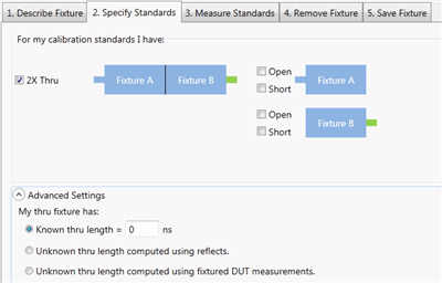
2. Specify StandardsNote: AFR Config and 2X Thru for N is a Licensed Feature. Learn more about Licensed Features.
Selecting 2 single-ended ports, or 4 differential ports allows a 2X Thru choice.
Checking Use THRUs in the 1. Describe Fixture tab allows 2X Thru choice for a Multiport measurement.
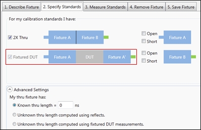
If My characterization fixture ≠ DUT measurement fixture is checked in the 1. Describe Fixture tab, the Fixtured DUT choice is displayed and checked.
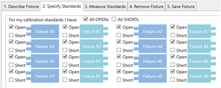
Otherwise, the fixture MUST be characterized using 1-port fixture measurements using either OPEN or SHORT terminations.
Note: The term 'Standards' is used here because this process can be thought of as the second in a '2-tier' calibration. The first tier of the calibration must already be performed (the VNA calibrated) before starting the AFR process. Another way of describing this step would be: "How will you be measuring or loading the characterization of the Thru standard?"
Notes:
Advanced Settings This setting is used to describe any ADDITIONAL length between the halves of the Thru or added to either of the individual halves. If the electrical length of the Thru standard is identical to the test fixture, then make no changes to the default settings (Known length = 0). My Thru fixture has:
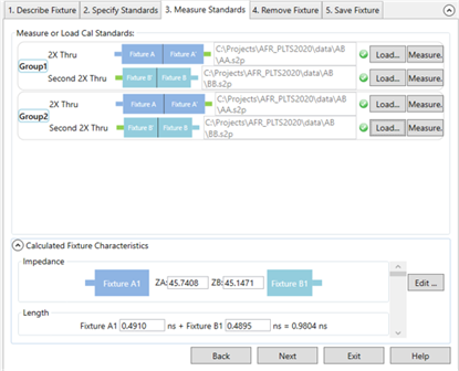
3. Measure Standards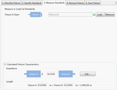
The following dialog is for Multiport 2X Thru measurements when Use THRUs is checked in the 1. Describe Fixture tab.
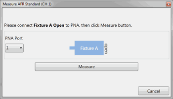
This step characterizes the 1X or 2X Thru standards. This is done by either performing measurements or by loading one or more *.snp files that describe the characterization of the fixtures. Note: When loading standards from files, the typical system characterization impedance (Z0) value is used, which is 50 Ω. Click Measure to see the following dialog: For best results, the analyzer should be calibrated. Also, the measurement Start and Step frequencies should be equal. This is necessary for TDR measurements. Connect the specified standard at the PNA port. Then click Measure.
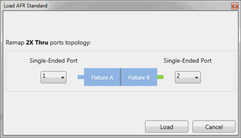
OR click Load and navigate to the *.snp file that describes the standard. For 2X Thru standards, the following dialog allows you to optionally remap the fixture ports.
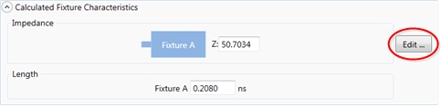
Calculated Fixture Characteristics Note: The fixture length must be 4 times the rise time. If not, an error message will be displayed. For example, a measurement at 26.5 GHz has a rise time of 37.7 ps. Therefore, the fixture length must be 4 * 37.7 ps = 151 ps. The loaded or measured Impedance and Electrical Length of the fixture are calculated and displayed here. The preview button allows you to visualize the time domain characteristics of the fixture model that will be used for de-embedding. By using the editing features noted below, the output match, length, and impedance of the fixture model can be optimized. This allows flexibility for including or excluding physical characteristics such as excess inductance of plug fingers, excess capacitance of receptacle pads or any other anomalies not desired in the fixture model. This advanced feature should be used with care as misuse could cause passivity or causality errors in the resultant fixture model.
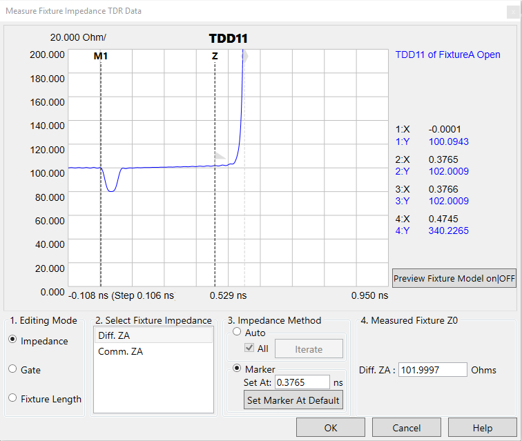
Click Edit to start the following, interactive Measure Fixture Impedance TDR Data dialog.
This dialog allows you to change the Impedance and/or Fixture Length of the saved *.snp data by moving a marker to the desired location on the TDR plot.
Editing Mode. (For 2X Thru, Fixture Length can NOT be changed.) Choose one or more of the following to edit the data in resulting *.snp files:
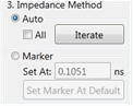
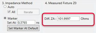
Select Fixture Impedance - Select the A or B fixture. Impedance Method - Select Auto then click Iterate to measure the fixture Z0 automatically and return fixture impedance back to 50 Ω. If more than one fixture impedance needs to be measured, check All to measure all impedances listed in Select Fixture Impedance. Select Marker to measure the fixture Z0 manually using the Z marker. The Set At field shows the X-axis position of the Z marker in ns. The Set Marker At Default returns the Z marker and fixture impedance to the default value.
Measured Fixture Z0 - Shows the measured fixture impedance. When Marker is selected as the Impedance Method, this field displays the current Z marker value or a value can be entered directly in this field. When Auto is selected as the Impedance Method, this field displays the fixture impedance value that was found automatically after clicking the Iterate button. In Auto, moving the Z marker will not change this value. Diff: ZA: - Enter the AFR fixture impedance manually using the text box.
Fixture Length Editing Mode Select Fixture Impedance - Select the A or B fixture. Set Marker Position, Gate Position, or Fixture Length depending on the selected Editing Mode. Move the marker (M1, Gate flag, or diamond) to the desired response on the trace. Set At Default - PLTS chooses an appropriate length at which to set the initial impedance or length. Click to return the marker to this location.
Preview ON/off - Select Off, then ON to preview the new measurement. Click OK when finished. When saved, the new Impedance and Length results are copied to the *.snp files.
4. Remove Fixture
Note: First choose Select correction method, then make other selections, then click Apply Correction. Both operations can be performed, but only one at a time.
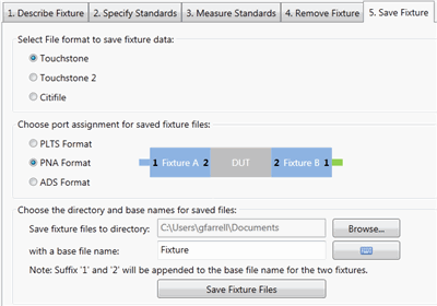
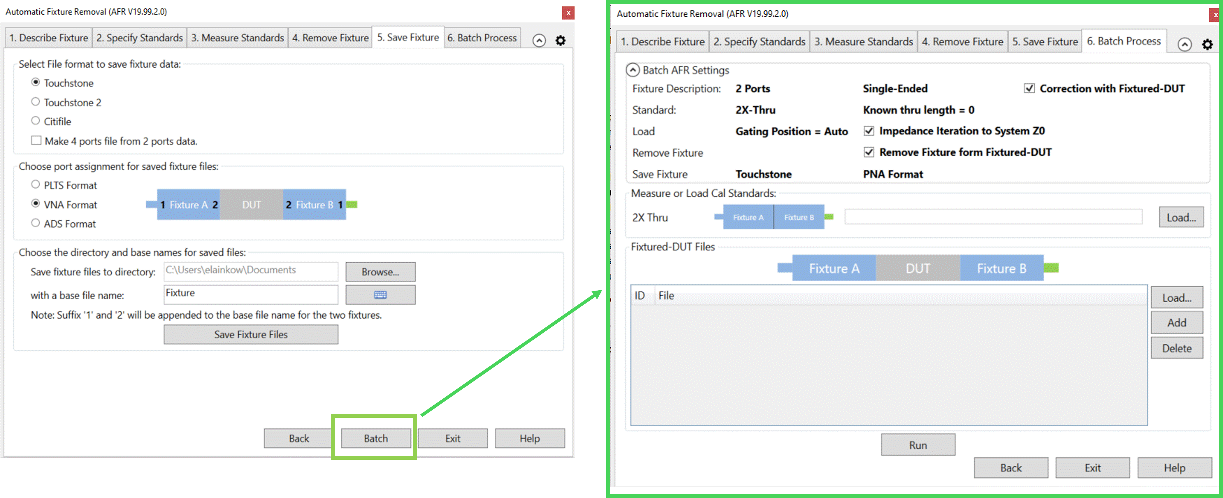
5. Save Fixture
Select File format to save fixture data:
Choose port assignment for save fixture files: The port assignments are interpreted differently when the file is opened in each program. Choose which program software you will be using to open the saved file: PLTS, VNA, ADS.
Choose the directory and base names for the saved files: Click Browse to navigate to a directory folder. With a base file name: The resulting filename will appear as follows (assuming a Touchstone format):
Click Save Fixture Files to save the files to the specified directory.
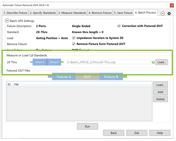
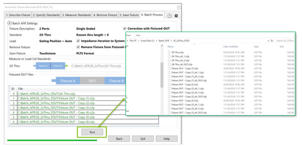
6. Batch Process
Batch AFR facilitates the AFR when you have multiple fixtured-DUTs with the same 2x-Thru standards. You do not need to repeat the AFR wizard steps with batch process.
Batch AFR use the settings summary from previous AFR wizard steps.
Measure or Load standards are the 2x-Thru standards of fixture. The default is the standard specified by previous AFR wizard. You can also load a different one by clicking the Load button.
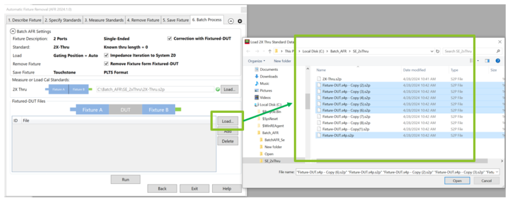
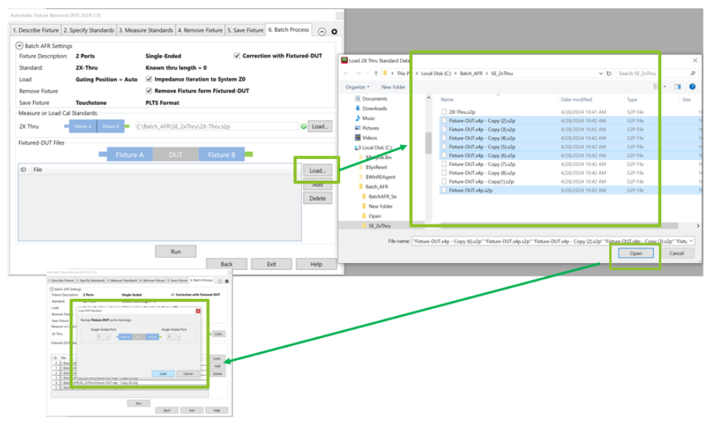
Click Load to import all the fixtured-DUT files.
Click Load to import all the fixtured-DUT files. All fixtured-DUTs will use the same topology.
Click Run. The batch process saves the fixture with appendix _afr_1 as left fixture , _afr_2 as right fixture, and _afr_DUT as de-embedded DUT.
|
|||


 appears as the 2X Thru when you select