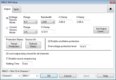
Either Voltage or Current Source Mode can be selected by toggle switch
Voltage Source Mode Selects voltage priority mode.
-
Range Selects 6-V or 13-V output range.
-
Bandwidth Selects one of four source bandwidths. To avoid output oscillation, ringing, overshoots, and poor transient response, refer to the following table for the correct bandwidth setting. The Low setting is the most stable, but has the slowest response. The High settings provide faster response times for the specified load capacitances.
|
Bandwidth Setting |
Sensing |
Load Capacitance (CL) |
ESR @100 kHz |
Maximum distance from sense point to load capacitance (SB) |
|
Low |
Local or remote |
0–150 μF |
50 to 200 mΩ |
Full lead length |
|
High1 |
Remote only |
0–1 μF |
50 to 200 mΩ |
15 cm |
|
High2 |
Remote only |
1–7 μF |
50 to 200 mΩ |
15 cm |
|
High3 |
Remote only |
7–150 μF |
50 to 200 mΩ |
15 cm |
-
+I Clamp Sets the positive current limit. When the output source level exceeds this, the trace is clipped.
-
-I Clamp Sets the negative current limit. When the output source level exceeds this, the trace is clipped.
Current Source Mode Selects current priority mode.
-
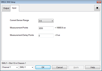
Range Selects 1-mA or 3-A output range .
-
V Clamp Specifies the voltage limit. When the output source level exceeds this, the trace is clipped.
Protection Status Show the current output status: Source On or Off
Reset Protection Resets a protection trip, after you clear the cause of the trip
Refresh Status Update the latest protection status.
Enable oscillation protection Enables or disables protection against oscillation of the output. This setting is used for all channels.
Overvoltage protection level Specifies the value at which overvoltage protection trips
Lock output relay closed for all channels When this box is checked, the relay in SMU is always closed even output is enabled or disabled. This function avoids its mechanical relay from abrasion. This setting is used for all channels.
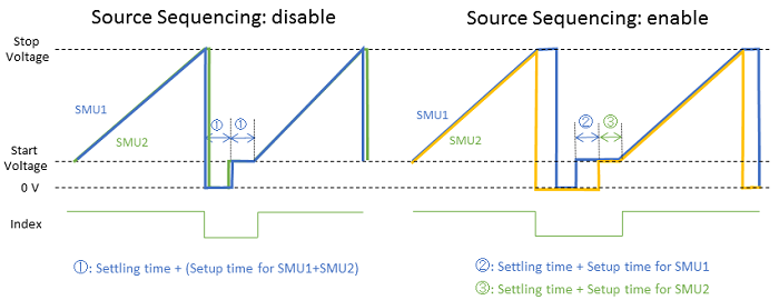
Enable Source Sequence:
-
Enable: At the beginning of the channel, it will turn on SMU outputs in order from lowest number to highest number, waiting the "Source Settling Time" between each SMU. At the end of the channel, it will turn off SMU outputs in order from highest number to lowest number, waiting the Source Settling time between each SMU.
-
Disable: the SMUs will be turned on and off in the same order as described above, but there will be no settling time between the SMUs. However, the "source settling time" will be used to calculate the time to wait at the beginning of sweep after all SMUs are turned On and at the end of sweep after all SMUs are turned Off.
-
This is set per-channel and the same for all SMUs.
Settling time:
-
When the source voltage or source current is enabled/disabled/changed at the beginning or end of the sweep,
-
-
The VNA will check to see when it has settled, tThen it will wait the additional time indicated by the "Source Settling Time" before continuing with the measurement.
-
Note that if the source is turned off at the end of the sweep, then the VNA will wait for this settling time before continuing with the next sweep.
-
-
"Settling Time" only affects timing at the beginning and end of the sweep. If the SMU output is changed during a sweep (per point), the "Settling Time" does not affect the settling timing for each point.
-
This is set per-channel and the same for all SMUs.
Channel Specifies the target channel to setup.
SMU Specifies the target SMU to setup
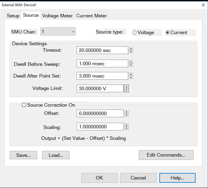
Set Output Level Open DC Source Dialog box to specify the output level