DC Source Control
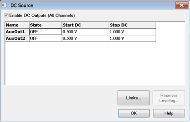
When a DC Source (power supply) is configured as an external device and an internal device, the new DC source can be controlled from the VNA using this dialog. Internal DC Sources are also controlled from this dialog.
See Also
Configure the DC Source as an External Device
Internal DC Sources - ADC Measurements
Other Setup Measurements Topics
|
Name Lists the names of the configured DC Sources. In the above image:
State Set the state of the DC source.
Start / Stop DC Set the start and stop voltages of the DC source. The VNA will step the voltage of the DC source from Start to Stop in increments = (Stop - Start)/Number of data points. ButtonsLimits Click to start the DC Limits dialog. Receiver Leveling For future use. |
|
Select the Minimum and Maximum voltages to which the specified DC sources can be set by the VNA. When the DC source level exceeds the limit, DC source is turned off and the measurement sweep stops. For M9485A only, DC source is clumped at the limit level and the measurement sweep continues. Note: When the M9341B is not located at the next slot of the most right receiver (M9378A/B can be placed between M9377A and M9341B), the measurement speed may be slower. In this configuration, the DC source level exceeding makes sweep stop and DC source off.
|
|
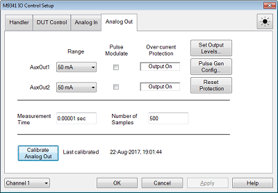
This tab is displayed only when the M9341B is installed. Note (M9485A): The M9341B should be placed at next slot of the most right receiver (M9376A/77A). For the M9377A, the M9378A/B can be placed between M9341B and M9377A. Otherwise, the measurement speed becomes slow.
Range Selects the current range of output from 50 m or 500 mA Pulse Modulate Enable the pulse modulation for Analog output signal. The Analog output signal is output synchronized with the pulse signal which is inputted into SMB Sync 4 port on the M9341B. When the basic RF pulse measurement option (025) is installed, connecting SMB sync 4 and any connector from P1 to P4 allows you to make a pulsed AUX output with the internal pulse signal. When the option is NOT installed, only AuxOut can be pulse modulated and the external pulse signal is required. Over-current Protection Shows the status of signal output, Output On or Output Off. Note that when the protection turns off the output, the "DC Source" dialog the state of the analog output may still indicate that it is "on" because this state is independent of the protection. Set Ouput Levels Displays DC source dialog box to define the DC source. Pulse Gen Config... Displays Pulse Setup Dialog box to define the internal pulse signals. This button is displayed and available only when the pulse basic RF pulse measurement option (025) is installed. Reset Protection Resets the over-current protection for all channels Measurement Time Specifies the measurement time. This can calculated by (Number of Samples) x 20 nsec. This is the same entry in Analog In Tab. Number of Samples Specifies number of ADC samples for one point. One ADC sample takes 20 nsec. Increasing this number improves the stability of DC measurement. This is the same entry in Analog In Tab. Calibrate Analog Out Executes the analog out calibration. No setup is required for calibration. Validation of calibration: 1 hour and ±3 cº from previous calibration.
|