DUT Control and 8 bit Digital I/O

PXI VNAs with M9341B can control the device under test (DUT) directly with serial or parallel digital signals. For example, the signals from the M9341B can be applied to select operation modes of the RF front-end module which integrates power amplifiers, switches, low noise amplifiers, duplexer or filters in a single component. The operation can be synchronized with the sweep of VNA measurement.

Signa from 8-bit I/O can provide up to 4-channels RFFE-like interface with software selectable clock rate (25 MHz maximum).

The following five commands are supported.

See also

How to configure DUT control and 8 bit digital I/O


Using Hardkey/SoftTab/Softkey

Using a mouse

  1. Press Setup > Internal Hardware > PXI Device...

  2. Click M9341 IO Control Setup.. to control the M9161Der.

  1. Click Instrument

  2. Select Setup
  3. Select Internal Hardware

  4. Select PXI Device..

  5. Select  M9341 IO Control Setup..


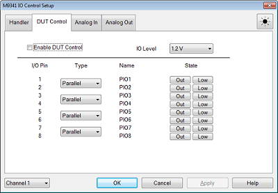
DUT Control dialog box help

This tab is displayed only when the M9341B is installed.

See IO Module Front Panel for 8 bit I/O port pin assignment and schematic.

Enable DUT Control  The settings are applied for the selected channel. The I/O configuration is independent for each channel.

IO Level  Set the voltage level of Vout (ST40X Pin No. 9). This level defines the "HIGH" logic level of all I/O pins. The value range is 0.9 to 3.5 V with 0.05 V resolution.

Type  Eight I/O pins are consists of 4 group of 2-pins pair: (Pins No. 1 and 2), (Pins No. 3 and 4), (Pins No. 5 and 6), (Pins No. 7 and 8). Each group can be assigned with Parallel or RFFE

Name: The name of assigned signal.

State  

  • When Parallel is selected:

    • In or OUT -  Select the pin function from Input or Output.

    • Low or High - For input pin, show the current state. For output pin, select the level from Low or High

  •  When RFFE is selected:

    • Clicking RFFE setup.. shows the RFFE setup dialog box.


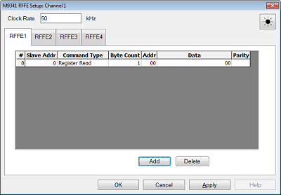
RFFE Setup dialog box help

#  RFFE command sequence number up to 16

Clock Rate  Specify the clock rate from 25 kHz to 25 MHz. Possible values are 50000/n, with integer n, 2000 to 2.

Slave Addr  Specify the slave address in decimal. The slave address should be from 0 to 15 (4 bits).

Command Type  Select the RFFE command sequence type.

  • RREad: Register Read

  • RWRite: Register Write

  • ERRead: Extended Register Read

  • ERWRite : Extended Register Write

Byte Count  Specify byte count value in decimal. The value range is depending on command sequence type setting.

Command sequence type

Byte count range

Register 0 Write

Register Read

Register Write

1

Extended Register Write

Extended Register Read

1 to 16


Addr Specify the address value in hex Integer value. The value range is coupled with command sequence type setting.

Command sequence type

Addr range

Register 0 Write

0 (fixed)

Register Read

Register Write

#h00 to #h1F (0-31)

Extended Register Write

Extended Register Read

#h00 to #hFF (0-255)


Data  Specify or read the data in hex value. Comma separated of data values. The value length is coupled with byte count setting

Parity  Show the parity value for each data.