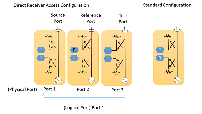
You can make a Direct Receiver Access (DRA) Configuration when you use three ports of M980xA, P50xxA/B, P93xxB in order to make a better dynamic range and high power measurements. A sets of three physical ports are assigned as Source, Reference and Test ports, then they can be worked as one logical port.

Note: When the macro button is not available, execute “C:\\Program Files\Keysight\Network Analyzer\Service\PortConfiguration.exe”
Port Configuration dialog box help |
# of VNA physical ports: the number of the detected physical port in your system # of DRA ports: The number of DRA ports you require. Set at 0 to return to the standard mode for all ports. This should be greater than or equal to (# of DRA ports) * 3. The table shows the logical port assignment. The DRA ports are assigned from the physical port 1. Hence, the STD ports come after DRA ports. In the case above, the physical ports from 1 to 3 are assigned source (S), reference (R), and test (T), respectively, then make them logical port 1. Note: DRA is displayed at status bar. DRA mode survives a Preset or Shutdown. Note: Only the first instance can be assigned as a DRA configuration. Note::A is displayed at status bar. DRA mode survives a Preset or Shutdown. |
When the M981xA Receiver Module is installed, the Port Configuration dialog box shown above is not used.
Instead, a port configuration file is required to modify.
Follow the procedure below.
After the multi module configuration is done, click the Network Analyzer icon to execute the launcher.
Select all required modules
for both M980xA VNAs and M981xA Receivers.
Note: The description of M981xA modules
is shown as "M980xA", not "M981xA".
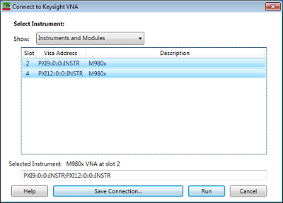
Click Run.
The following message is displayed.
Then click Ok.
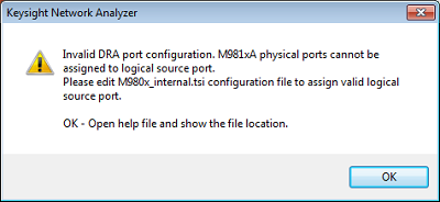
The Help (this page) and the
file explore are opened. The C:\\ProgramData\Keysight\Network Analyzer\data<n>\Testsets\M980X_internal.tsi
is shown in the file explore.
Note: The firmware assigns <n>
in data<n> directory to each configuration. When the configuration
is changed. the number <n> will be changed. :SYST:CONF:DIR
SUPP returns the directory for the current
configuration.
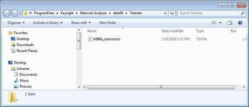
Modify the M980X_internal.tsi file according to the syntax below, then save the file.
The VNA application will be closed.
Click the Network Analyzer icon to execute the launcher.
Select the same modules, then click RUN.
The ports on the M981xA receiver must be assigned as either R (Reference) or T (Test).
The ports on the M980xA VNA can be assigned as S (Source), R (Reference) or T (Test).
The port number is assigned automatically from the left to the right.
Note: The port configuration application (macro) does not show the correct port assignment when .tsi file is used.
Here is some examples of the port configuration file.
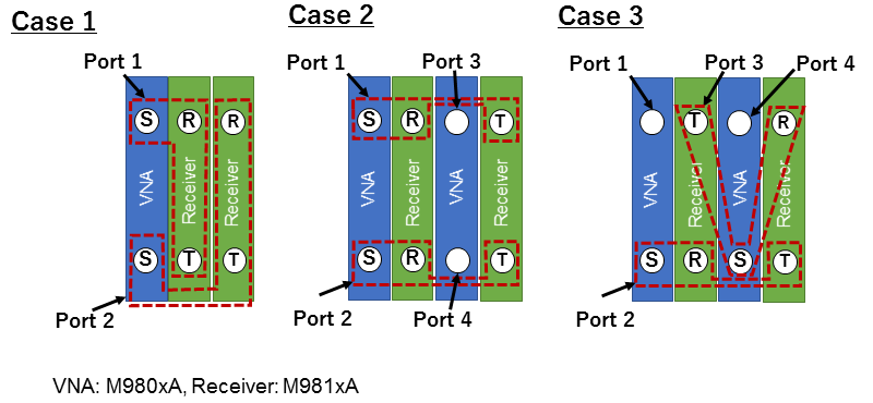
Case 1
<?xml version='1.0' encoding='UTF-8' ?>
<M980X>
<physicalports>6</physicalports>
<dra numports ='2'>
<draports src='1' rcv_r='3' rcv_t='4' />
<draports src='2' rcv_r='5' rcv_t='6' />
</dra>
</M980X>
Case 2
<?xml version='1.0' encoding='UTF-8' ?>
<M980X>
<physicalports>8</physicalports>
<dra numports ='2'>
<draports src='1' rcv_r='3' rcv_t='7' />
<draports src='2' rcv_r='4' rcv_t='8' />
</dra>
</M980X>
Case 3
<?xml version='1.0' encoding='UTF-8' ?>
<M980X>
<physicalports>8</physicalports>
<dra numports ='2'>
<draports src='2' rcv_r='4' rcv_t='8' />
<draports src='6' rcv_r='7' rcv_t='3' />
</dra>
</M980X>
The two physical ports can be assigned to one logical port. This feature supports only 2 port VNAs. 4-6 ports VNAs are not supported.
Example
Logical Port 1:
Source and Reference: Physical Port 1
Test: Physical Port 2
Logical Port 2:
Source and Reference: Physical Port 2
Test: Physical Port 1
<M980X>
<physicalports>2</physicalports>
<dra numports ='2'>
<draports src='1' rcv_r='1' rcv_t='2' />
<draports src='2' rcv_r='2' rcv_t='1' />
</dra>
</M980X>