Turn on M9379A amps for all channels: Master switch for all amplifiers and switch of all M9379A modules. LED on the front panel is changed as follows.
ON: Dark green
OFF: Light green
Note: 45-minute warm up time after this switch ON is required to meet the specification accuracy.
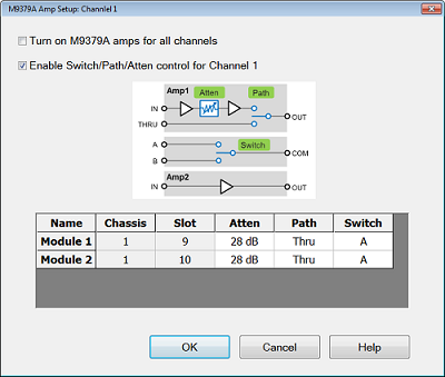
Enable Switch/Path/Atten control for Channel n: The settings are applied for the selected channel. The setting of Switch/Path/Atten is independent for each channel.
Name: Module number.
Chassis: Chassis number where the module is located.
Slot: Slot number where the module is located.
Atten: Attenuator setting for the amplifier 1. This can be set from 0 to 28 dB with 2 dB step.
Path: Path for amplifier 1. Select Thru or Amp. When Noise Figure Cold Source is selected as Meas Class, NF Receiver can be selected.
NF Receiver: The switch is used for pre-amp/thru selection between DUT and test port n. The Thru is selected during S parameter measurement. The Amp is selected during NF measurement.
Switch: Path for switch. Select A or B. When Noise Figure Cold Source is selected as Meas Class, NF Source, NF LO or NF Receiver can be selected.
NF Source: The switch is used as RF Out switch to terminate the DUT input with 50 ohm. RF out should be connected with port A. 50 ohm termination should be connected with port B. The port A is selected during S parameter measurement. The port B is selected during NF measurement.
NF LO: The switch is used as Local selection for dual band NF measurement. (Option 720 only)
NF Receiver: The switch is used for pre-amp/thru selection between DUT and test port n. The port A is selected during S parameter measurement. The port B is selected during NF measurement.
Note: Control the gain of M9379A properly in order to avoid saturation and overload from receivers due to amplified source signal noise by the M9379A. When the M9379A Amp1 is used with the M9377A DRA modules (receiver attenuator = 0 dB), It is recommended that the M9379A Amp1 attenuator sets at 10 dB or above. When the M9379A Amp2 is used, inserting 10 dB attenuator between Amp2 and the M9377A is recommended.