Error Correction and Interpolation settings work together to provide you with the highest level of calibration accuracy possible.
How to set Error Correction |
Using Hardkey/SoftTab/Softkey |
|
The Error Correction ON setting means that the calibration error terms are applied to the measurement. Error Correction is automatically turned ON when a calibration is performed or if a Cal Set is applied to a measurement. The VNA attempts to turn error correction ON for ALL of the measurements on the active channel. This may not always be possible when applying Cal Sets. For more information, see Applying Cal Sets.
When full 2-port error correction is ON, both forward and reverse sweeps are required to gather all 12 error terms, even if only one reflection measurement is displayed. This may result in a higher measurement speed than expected. Learn more.
You can always turn Error Correction OFF for the active measurement by clicking Correction OFF. The VNA will turn Error Correction OFF automatically when making stimulus changes under some conditions. To turn correction back ON, click Correction ON. Then:
If Interpolation can NOT be performed, a dialog box will ask if you would like to change the stimulus settings to those of the applied calibration. Click OK or Cancel.
If Interpolation can be performed, the stimulus setting will change and correction turned ON.
How to set Factory Error Correction |
Using Hardkey/SoftTab/Softkey |
|
The factory calibration is a calibration which is done at the factory shipment or service centers for periodical calibration.
The correction level provides information about the accuracy of the active measurement. Correction level notation is displayed on the status bar for different calibration types like response, full 2-port, TRL, or power calibration.
Right-click in the display, select Customize Display, select Toolbars tab, then select Status Bar. The status bar appears and displays the following items:
Correction Level |
Accuracy |
|
C N-Port |
Full N Port |
Highest |
C Enh Resp |
Enhanced Response |
|
C Resp |
Response |
|
Factory |
Factory calibration at test port |
|
No Cor |
No Correction |
Lowest |
C* |
Interpolated |
Uncertain |
CD |
Changed |
Uncertain |
Full N Port correction, where N is the number of fully calibrated ports.
This correction is applied to SParameters.
If the calibration was performed with a receiver power cal, this correction can be applied to receiver measurements. (eg: a1, b1, A, R1, b1/a1). (See Correction Methods for the ability to control the level of calibration applied to receiver measurements).
Enhanced response cal is an aggregate of a 1 Port calibration and a transmission response cal.
This correction is applied to reflection and transmission parameters in either the forward direction (S11, S21) or the reverse direction (S12, S22) depending on how the calibration was performed.
For reflection measurements, Enhanced Response correction is equivalent to C 1-Port correction. For transmission measurements, the correction is equivalent to a match-corrected transmission response cal.
Response calibrations are one term calibrations that correct for the frequency response of the measurement. It does not correct for impedance mismatches.
The following will cause the VNA to turn Error Correction OFF for the channel:
Decrease the start frequency
Increase the stop frequency
Change start frequency, stop frequency, or number of points with Interpolation OFF.
The correction pop up pane, accessed by right-clicking on the Correction item in the status bar, indicates port by port correction methods for a VNA with 12 or less test ports. This table is updated when the port subset correction is turned on to reflect the correction methods being applied. In the image below, the pane indicates a full 4-port calibration. On the right, the table indicates the methods after the correction was devolved to ports 1, 2, and 3.
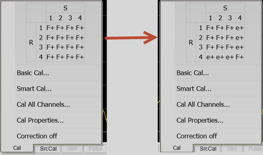
The F+ indicates that the port had the full error correction applied. The e+ indicates that the enhanced response correction method was applied to the port.
Note: For more information about port sub-setting, refer to Port Sub-Setting Examples.
"C star" appears in the status bar when a measurement is being interpolated. See Interpolation (above) and Interpolation Accuracy.
"C-delta" appears in the status bar when one or more of the following stimulus settings change.
The calibration is uncertain when the attenuator setting has changed. On the other hand, the other settings, such as sweep time or IF Bandwidth, do not invalidate the calibration.
If lowering IF bandwidths below the calibration's IF bandwidth, any trace noise present in the calibrated data due to the wider IF bandwidth will persist.
How to set Interpolation |
Using Hardkey/SoftTab/Softkey |
|
Interpolation
Calibration interpolation adjusts calibration error terms to match changes to the following settings that you make AFTER a calibration is performed or a Cal Set applied.
The Interpolation ON setting means that interpolation is enabled for the active measurement. This does not necessarily mean that the measurement is interpolated. When enabled (ON), if interpolation becomes necessary because you change any of the following stimulus settings, then interpolation will be applied. When stimulus settings change while interpolation is OFF, interpolation is NOT applied but instead, error correction is turned OFF.
Interpolation occurs (if enabled) when you change any of the following settings:
Start frequency increased
Stop frequency decreased
Number of points
Note: Decreasing the start frequency, or increasing the stop frequency will always turn correction OFF. (Exception: Power Calibration DOES extrapolate to the start and stop frequencies.)
When a measurement is interpolated, the accuracy of the measurements cannot be predicted. It may be affected significantly or not at all. Identifying measurement errors in these cases must be determined on a case-by-case basis. In general, the magnitude and phase stimulus from the VNA and the response from the DUT need to be smooth and continuous for measurement interpolation to give accurate results.
Significant measurement inaccuracy WILL occur when the phase shift response between measurement points increases changes more than 180 degrees. The VNA will incorrectly interpolate the new phase data. For more information, see phase accuracy.
In general, the chances of significant inaccuracy increases when interpolating measurements under the following conditions:
when frequency span between measurement points becomes much greater.
when measurement frequencies are above 10 GHz where phase changes happen more rapidly.
when interpolating across frequency band crossings. Learn more about band crossings.
Note: When the interpolation algorithm encounters an abrupt or large change in the response magnitude or phase, such as can occur at band crossings, large interpolation errors can be included in the displayed data. These errors can be seen as steps or spikes. If this occurs, consider turning off interpolation, changing the measurement parameters, or creating sweep segments that skip over the band crossings.