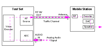
The real-time vocoder allows you to perform the audio test in two aspects:
Perform the functional test for the analog voice capability of the mobile station.
Calculate the audio input gain, audio output gain and internal codec loopback gain of the Test Set, which helps you to perform the acoustic measurement in 3GPP TS 26.131 and TS 26.132
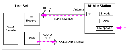
The real-time vocoder functionality allows you to perform the functional test for the analog voice capability of the mobile station when the Operating Mode of the real-time vocoder is set to Normal:
the test set can real-timely encode the analog audio signal applied at the test set's AUDIO IN connector using the appropriate vocoder algorithm (depending upon the selected voice service option) and then sends the encoded audio frames to the mobile station. See A Simplified Signal Flow for Real-Time Encoding.
Also, the test set can simultaneously decode the encoded audio frames that is received on the traffic channel using the appropriate vocoder algorithm (depending upon the selected voice service option) and then converts to an analog signal output at the test set's AUDIO OUT connector. See A Simplified Signal Flow for Real-Time Decoding.

The real-time vocoder functionality allows you to calibrate the audio output gain, audio input gain and internal codec loopback gain of the test set when the Operating Mode of the real-time vocoder is set to Calibration.
Audio Output Gain Calibration
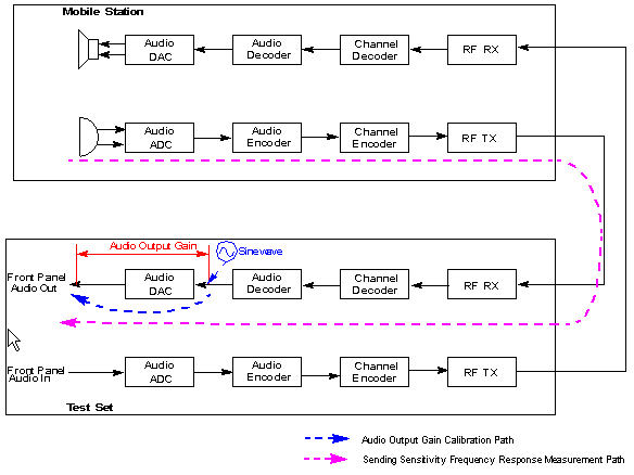
The audio output gain calibration is performed when the Calibration Type is set to Audio out Path. The test set sends a full scale sinewave to the AUDIO OUT port. The audio output gain can be determined by measuring the output analog signal.
The audio output gain calibration result helps to perform the acoustic measurements of the mobile station, for example, the sending sensitivity frequency response.
Audio Output Gain Calibration
Audio Input Gain Calibration:
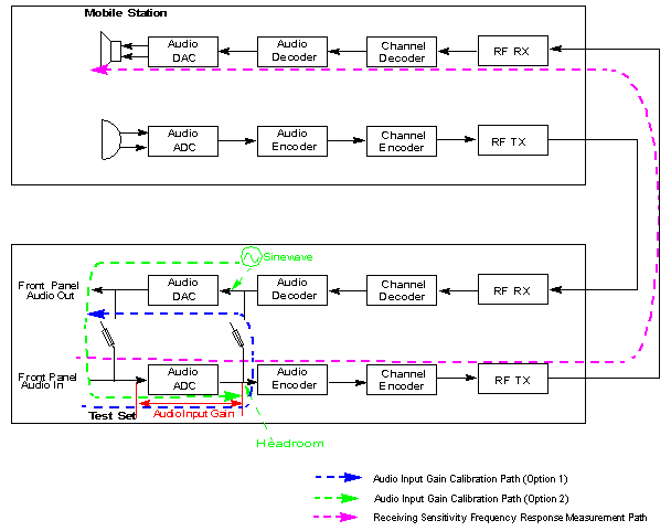
You can get the audio input gain of the test set in two ways:
Option 1: Set the Calibration Type to Audio In Path. The test set samples the input signal from the AUDIO IN port and loops them back to the AUDIO OUT port via the DAC. If an audio output path calibration has already been done, the audio input gain can be derived from the loopback gain and the audio output gain.
Option 2: Set the Calibration Type to Audio Out Path, looping the full scale sinewave from the AUDIO OUT port to the AUDIO IN port. As the audio output gain can be obtained by audio output path calibration, the audio input gain can be determined by reading the Encoder Headroom.
The audio input gain calibration result helps to perform the acoustic measurements of the mobile station, for example, the receiving sensitivity frequency response.
Audio Input Gain Calibration
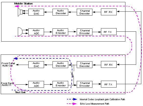
Internal Codec Loopback gain Calibration
The internal codec loopback gain calibration is performed when the Calibration Type is set to Internal Codec. The test set samples the input signal from the AUDIO IN port, encodes the samples with the voice encoder and loops them back to the voice decoder, then sends the signals to the AUDIO OUT port via the DAC.
The internal codec loopback gain calibration result helps to perform the acoustic measurements of the mobile station, for example, the echo loss.
Internal Codec Loopback gain Calibration
The following parameters can be set from the Real-Time Vocoder Parameters menu. To access the Real-Time Vocoder Parameters menu, see How Do I Use the Real-Time Vocoder.
Sets the peak voltage of the analog audio signal that is applied at the test set's AUDIO IN connector when the test set is in the real-time vocoder mode. It is used to adjust the audio input path gain for real-time encoding. Whenever you change this setting, it is not applied until the test set is set to the real-time vocoder mode.
GPIB command: CALL:RTVocoder:INPut:VOLTage[:EXPected][:SELected]
Sets the maximum peak voltage of the analog audio signal that is expected to output at the test set's AUDIO OUT connector when the test set is in the real-time vocoder mode. Whenever you change this setting, it is not applied until the test set is set to the real-time vocoder mode.
Setting this value makes the test set adjust the audio output path gain to achieve the desired audio output level at the test set's AUDIO OUT port. However, the actual output signal also depends on the voice signal decoded from the received voice data. The decoded signal may not be normalized to DAC (Digital to Analog Converter) full scale range. So it is possible that the final signal level is lower than the configured level.
GPIB command: CALL:RTVocoder:OUTPut:VOLTage[:MAXimum][:SELected]
Sets the VAD Algorithm used in the speech codec. The process of separating conversational speech and silence is called the Voice Activity Detection (VAD). The primary function of a voice activity detector is to provide an indication of speech presence in order to facilitate speech processing as well as possibly providing delimiters for the beginning and end of a speech segment. Refer to 3GPP TS 26.094 section 3 and 4 for more information about the VAD options.
GPIB Command: CALL:RTVocoder:VADetection:AMRate:ALGorithm[:SELected]
Sets whether or not the voice activity detection is implemented in the speech codec.
GPIB Command: CALL:RTVocoder:VADetection[:STATe][:SELected]
Sets the operating mode of the Real-Time vocoder.
When Normal is selected, you can perform the normal functional test for the analog voice capability of the mobile station.
When Calibration is selected, you can calibrate the audio input gain, audio output gain and the internal codec loopback gain of the test set.
GPIB Command: CALL:RTVocoder:OPERating:MODE
When the Operating Mode is set to Calibration, Calibration Type determines whether the audio output path, the audio input path or the internal codec loopback gain of the test set is calibrated.
GPIB Command: CALL:RTVocoder:CALibration:TYPE
When the Operating Mode is set to Calibration and the Calibration Type is set to Audio Out Path, Audio Out Frequency sets the frequency of the sinewave sent out by the test set.
GPIB Command: CALL:RTVocoder:OUTPut:FREQuency
The following results are displayed on the Real-Time Vocoder Information window when a voice call is established and the test set is in the real-time vocoder mode.
Indicates the headroom of the audio samples to the full scale of the ADC (Analog to Digital Converter). This result is updated at about one second period and calculated as follows:
Encoder Headroom (dB) = 20 *Log ((ADC full scale) / (maximum absolute value of the input sample))
When the input signal is over-range, the headroom is clipped to zero.
GPIB command: CALL:RTVocoder:ENCoder:HEADroom[:SELected]
Indicates the headroom of the decoded data samples to the full scale of the DAC (Digital to Analog Converter). This result is updated at about one second period and calculated as follows:
Decoder Headroom (dB) = 20 *Log ((DAC full scale) / (maximum absolute value of the output sample).
GPIB command: CALL:RTVocoder:DECoder:HEADroom[:SELected]
The Operation Mode is set to Active Cell to use with the real-time vocoder.
The real-time vocoder works along with the complementary Digital Audio Interface to perform live end to end testing (including microphone and loudspeaker if desired).
The real-time vocoder supports all current Speech Channels.
The test set is configured in real-time vocoder mode when the Speech Source is set to Real-Time Vocoder.
When a voice call is established with the AMR Source to be Real-Time Vocoder, it is highly recommended that you should not run any measurement at the same time, except for the Channel Power measurement.
When the AMR Source is set to Real-Time Vocoder, you can not change the audio source parameters such as output level and the source to be routed to the AUDIO OUT connector (see AFGenerator Subsystem).
When the input signal is over-range, the headroom value is equal to zero.
When the Expected Audio In Peak Voltage parameter is changed, you re-calibrates the audio input gain.
When the Maximum Audio Out Peak Voltage parameter is changed, you re-calibrates the audio output gain.
How Do I Use the Real-Time Vocoder