Programming the Dynamic Power Analysis Measurement
Last updated: January 16, 2009
The following program example assumes that the UE is connected to the RF IN/OUT connector.
The basic procedure to perform a
Dynamic Power Analysis
measurement (for UE power calibration) is as follows:
- Set the test set's receiver to the proper power and frequency using the RFANalyzer:CONTrol:POWer:AUTO , RFANalyzer:MANual:POWer[:SELected] and RFANalyzer:MANual:MEASurement[:MFRequency] commands.
- Set the Dynamic Power Analysis setup parameters to match your UE's power sequence using the SETup:WDPAnalysis commands.
- Arm the measurement using the INITiate:<measurement mnemonic>[:ON] command.
- Prompt the user to place the UE into a test mode which will force it to continuously transmit the power sequence you desire to test.
- FETCh the measurement results using the FETCh:WDPAnalysis commands.
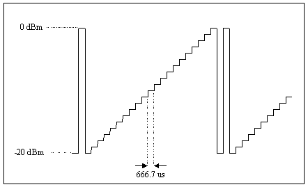
The example below assumes a power sequence as follows:

Programming Example
10 ! *** WDPAnalysis Programming Example ***
20 !
30 ! This programming example assumes the UE is connected to the test set
40 ! and prepared to send a power sequence that consists of a trigger pulse
50 ! that moves from -20 dBm to 0 dBm to -20 dBm, then steps in 1 dB
60 ! increments from -20 dBm to 0 dBm.  Each step is 1 timeslot in length.
70 ! The UE must continuously repeat this power sequence.
80 !
90       CLEAR SCREEN
100       DIM Wdpa_res$[3400]
110       DIM Wdpa_val(200)
120       Testset=714
130 !
140 ! *** Set up the test set ***
150 !
160       OUTPUT Testset;"RFANalyzer:MANual:MEASurement 1950 MHZ"
170         ! Sets Measurement Frequency to 1950 MHz
180       OUTPUT Testset;"RFANalyzer:CONTrol:POWer:AUTO OFF"
190         ! Sets Power Control to Manual
200       OUTPUT Testset;"RFANalyzer:MANual:POWer 0 DBM"
210         ! Sets Manual Power to 0 dBm
220 !
230 ! *** Set up measurement parameters ***
240 !
250       OUTPUT Testset;"SETup:WDPAnalysis:STEPs 23"
260         ! Sets Steps to 23
270       OUTPUT Testset;"SETup:WDPAnalysis:LENGth 666.7 US"
280         ! Sets Step Length to 666.7 us (1 timeslot)
290       OUTPUT Testset;"SETup:WDPAnalysis:INTerval 300 US"
300         ! Sets Measurement Interval to 300 us
310       OUTPUT Testset;"SETup:WDPAnalysis:TRIGger:THReshold -10 DBM"
320         ! Sets RF Rise Trigger Threshold to -10 dBm
330       OUTPUT Testset;"SETup:WDPAnalysis:RRCfilter ON"
340         ! Sets RRC Filter to On
350       OUTPUT Testset;"SETup:WDPAnalysis:FOFFset 0 HZ"
360         ! Sets Frequency Offset to 0 Hz
370       OUTPUT Testset;"SETup:WDPAnalysis:TRIGger:QUALify:STATe ON"
380         ! Sets Trigger Qualification State to On
390       OUTPUT Testset;"SETup:WDPAnalysis:TRIGger:QUALify:TYPE RISEFALL"
400         ! Sets Trigger Qualification Type to RF Rise and Fall
410       OUTPUT Testset;"SETup:WDPAnalysis:TRIGger:QUALify:RISE 10 DB"
420         ! Sets Trigger Qualification Rise Threshold to 10 dB
430       OUTPUT Testset;"SETup:WDPAnalysis:TRIGger:QUALify:FALL 10 DB"
440         ! Sets Trigger Qualification Fall Threshold to 10 dB
450       OUTPUT Testset;"SETup:WDPAnalysis:CONTinuous OFF"
460         ! Sets Trigger Arm to Single
470       OUTPUT Testset;"SETup:WDPAnalysis:TRIGger:SOURce RISE"
480         ! Sets Trigger Source to RF Rise
490       OUTPUT Testset;"SETup:WDPAnalysis:TRIGger:DELay 183.3 US"
500         ! Sets Trigger Delay to 183.3 us
510         ! (to place the Measurement Interval in the center of the timeslot)
520       OUTPUT Testset;"SETup:WDPAnalysis:TIMeout 10 S"
530         ! Sets Measurement Timeout to 10 s
540 !
550 ! *** Initiate the measurement ***
560 !
570       OUTPUT Testset;"INITiate:WDPAnalysis"
580       PRINT "Order UE to transmit its power sequence continuously"
590 !
600 ! *** Obtain measurement results ***
610 !
620       OUTPUT Testset;"FETCh:WDPAnalysis?"
630       ENTER Testset;Integrity,Numsteps,Wdpa_res$
640 !        ! FETChes the Integrity Indicator, number of power measurement
650 !        ! results available, and the power results
660 !
670 ! *** Print measurement results ***
680 !
690       PRINT
700       PRINT "Integrity Indicator = ";Integrity
710       PRINT "The number of power meas results available = ";Numsteps
720       PRINT
730       FOR I=1 TO Numsteps
740           Wdpa_mkr=((I-1)*17)
750             ! Sets up a marker that jumps to each comma in the ascii string
760           Wdpa_val(I)=VAL(Wdpa_res$[Wdpa_mkr+1;Wdpa_mkr+16])
770             ! Convert ascii to a numeric value
780           PRINT "Power of step";I;"= ";Wdpa_val(I);"dBm"
790       NEXT I
800 !
810       END
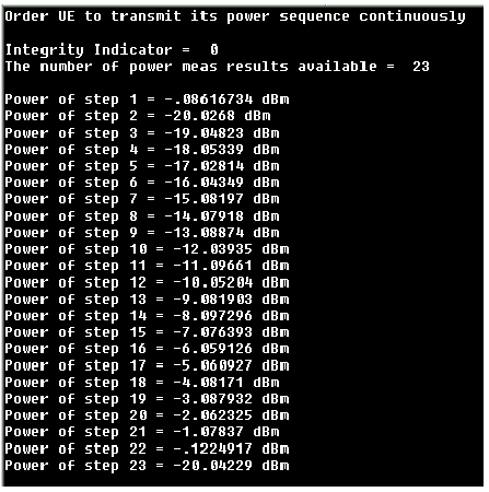
A sample output from this program example is shown below:

Related Topics
Dynamic Power Analysis Measurement Description