Dynamic Power Analysis Measurement Description
Last updated: January 16, 2009
- How is a Dynamic Power Analysis Measurement Made?
- Dynamic Power Analysis Measurement Parameters
- Dynamic Power Analysis Measurement Results
- Dynamic Power Analysis Measurement Input Signal Requirements
- Dynamic Power Analysis Measurement Calibration
How is a Dynamic Power Analysis Measurement Made?
The dynamic power analysis measurement is a flexible tool that allows you to measure the output power of your UE versus time. This section describes two main uses of the measurement:
- UE Power Calibration
- HSDPA/HSPA Power versus Time (lab application or feature-licensed test application only)
UE Power Calibration
The dynamic power analysis measurement is not performed with a call established between the test set and UE. Rather, you must place your UE into a test mode which forces it to continuously transmit the power sequence you desire to test, and then analyze the resulting UE output power using the test set.
The dynamic power analysis measurement can measure UE output power sequences that step up and/or down with varying or fixed power step sizes. The power step length, which must be fixed for the sequence, can be between 10 us and 12 ms (the measurement is specified for step lengths of 67 us to 12 ms). A total of 58.26 ms of power sequence can be analyzed (for example, up to 87 steps can be measured when
Step Length
is set to one timeslot (666.7 us)).
Off
or 40 dB when
RRC Filter
=
On
. To measure a power range greater than 40 dB, you must break the power range up into individual power sequences that do not exceed 40 dB, and perform the measurement for each power sequence.To use the measurement, you must first set Measurement Frequency to the expected UE transmitter frequency and set Manual Power to the maximum expected power for the sequence. You can perform the dynamic power analysis measurement in Active Cell Operating Mode or FDD Test Operating Mode . However, since this measurement does not utilize any overhead signalling to control the UE's power or frequency, you must manually set the test set's Expected Power and Measurement Frequency in either operating mode.
You must specify the length and number of steps in the sequence (including trigger pulses), configure the RF rise trigger, initiate the measurement, then order the UE to send its sequence continuously .
The measurement executes most efficiently if the UE transmits its power sequence continuously, until the measurement has completed. The measurement can be triggered externally or by an RF rise in the power sequence. Once triggered, the measurement captures the first power sequence, auto-ranges to the maximum power of the sequence, then triggers on and measures the next available power sequence. The time for the auto-ranging to complete varies depending upon the power sequence.
You can vary the
Measurement Interval
and its placement within each step (using the
Trigger Delay
setting), and insert or remove the
RRC Filter
. The measurement can analyze CW signals and uplink DPCH signals (when measuring CW signals, you must adjust the
RF Rise Trigger Threshold
setting accordingly and use the
Frequency Offset
setting to set the proper offset from the
Measurement Frequency
setting.)
Triggering the Dynamic Power Analysis Measurement for UE Power Calibration
You can trigger the dynamic power analysis measurement using an RF rise within the power sequence by setting
Trigger Source
to
RF Rise
and specifying the appropriate
RF Rise Trigger Threshold
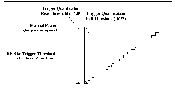
. If your power sequence starts with an abrupt rise in power, no separate trigger pulse is needed. However, for the most robust triggering, it is recommended that you include a trigger pulse in every power sequence. The trigger pulse should rise in power by at least 20 dB, reach the maximum power of the sequence, then fall in power by at least 20 dB. Before initiating the measurement, you must set
Power Control
to
Manual
and set
Manual Power
to the highest power expected in the sequence. It is then recommended that
RF Rise Trigger Threshold
be set to approximately 10 dB below the expected maximum power.
It is recommended that you also use trigger qualification, which allows you to further define the measurement trigger. Instead of the measurement triggering when the UE's signal simply rises above the
RF Rise Trigger Threshold
value, you can specify that the signal must meet some additional criteria before the measurement is triggered. To use trigger qualification, set
Trigger Qualification State
to
On
and set
Trigger Qualification Type
to
RF Rise
,
RF Fall
or
RF Rise and Fall
as appropriate for your power sequence. You must then set
Trigger Qualification Rise Threshold
and/or
Trigger Qualification Fall Threshold
accordingly. It is recommended that these rise/fall criteria be at least 10 dB.
Auto-ranging in the Dynamic Power Analysis Measurement for UE Power Calibration
To ensure successful auto-ranging, you must set the
Steps
setting equal or greater than the number of steps in the power sequence (including trigger pulses). When the measurement is triggered, the test set captures data for the time period specified by the
Steps
and
Step Length
setting to determine the power range of the sequence. It then ranges its receivers to accommodate the highest power in the sequence. The time for this auto-ranging to complete varies depending upon the number of steps in the sequence; a typical duration is approximately 500 ms (note that this is much greater than the duration of one power sequence). Once it has completed this auto-ranging, the test set re-arms and then is triggered by the next available power sequence. It then analyzes and reports the power of each step in that power sequence.
The measurement is most accurate over a 40 dB range (when
RRC Filter
=
On
). If the UE's power sequence spans more than 40 dB, the test set will measure and report the power of the entire sequence, but accuracy is degraded for steps that are more than 40 dB below the highest power in the sequence. To measure a power range greater than 40 dB, you must break the power range up into individual power sequences that do not exceed 40 dB.
To ensure that the measurement executes as quickly as possible, the UE should transmit its power sequence continuously until the measurement completes. This ensures that as soon as the measurement is done auto-ranging, another power sequence is immediately available for measurement.
Optimizing the Dynamic Power Analysis Measurement for UE Power Calibration
To help ensure your measurement routine executes as fast as possible, consider the following:
- Ensure that the UE is continuously repeating its power sequence.
- Use RF rise triggering, include a trigger pulse in the power sequence, and use trigger qualification to avoid false triggering.
- Make the trigger pulse equal to the maximum power in the sequence, to best utilize the 40 dB dynamic range of the measurement.
- Minimize the space between consecutive sequences (one step of space is sufficient).
- Note that a noisy UE signal may force the measurement to auto-range repeatedly.
HSDPA/HSPA Power versus Time ( lab application or feature-licensed test application only )
To perform power versus time measurements on an HSDPA or HSPA uplink signal, you must be on a
Radio Bearer Test Mode
connection with a
Channel Type
of
12.2k RMC + HSDPA
or 12.2k RMC + HSPA.
Dynamic Power Analysis Measurement Parameters
The dynamic power analysis measurement can capture up to 58.26 ms of power signal. Thus, the product of Steps and Step Length must not exceed 58.26 ms.
Specifying the Measurement Duration
-
Steps
You must specify the total number of steps to be measured.
The time duration of each step is determined by Step Length . If
Step Lengthis set to 666.666... us, then the number ofStepsto measure is equivalent to the number of timeslots to measure.For UE power calibration: the number of steps to measure must include any trigger pulses or separation steps included in the UE's power sequence. It is important that you set
Stepsequal or greater than the number of steps in your UE's power sequence so that the entire power sequence is evaluated during auto-ranging of the measurement (see Auto-ranging in the Dynamic Power Analysis Measurement for UE Power Calibration ). -
Step Length
For UE power calibration: this setting specifies the time duration of one step in the UE's power sequence (in seconds). Each step in the power sequence must be identical in length.
For HSDPA/HSPA power versus time ( lab application or feature-licensed test application only ): this setting specifies the time duration of one step, which determines how often a power measurement is made.
Step Lengthmust be greater than or equal to Measurement Interval .
Specifying the Measurement Characteristics for Each Step
-
Measurement Interval
When measuring the average power of each step, you can specify how long a period of time over which to average the power for each step using the
Measurement Intervalsetting. This setting is applied to the measurement of every step.Measurement Intervalmust be less than or equal to Step Length . -
Trigger Delay
When measuring the average power of each step, you can specify how long a period of time over which to average the power for each step using the Measurement Interval setting, and then place the measurement interval at the desired position within the step's duration in time using the
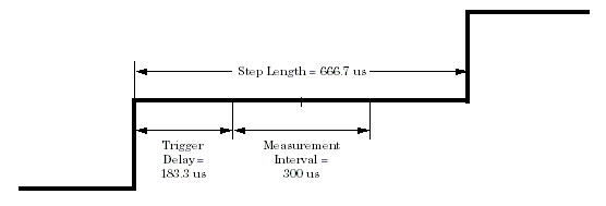
Trigger Delaysetting. In other words, theTrigger Delaysetting specifies how long after the start of the step the power measurement should begin. This setting is applied to the measurement of every step.For example, for UE power calibration, the default settings of
Step Length=666.7 us,Measurement Interval=300 usandTrigger Delay=183.3 uscauses the test set to measure power for 300 us centered in the middle of the step:For example, for HSDPA power versus time ( lab application or feature-licensed test application only ), setting
Step Length=666.7 us,Measurement Interval=616.7 usandTrigger Delay=25 uscauses the test set to measure power over the entire timeslot excluding the 25 us transient periods on either side of the slot boundaries: -
RRC Filter
You may choose to measure the average power of each step with or without the RRC (Root Raised Cosine) filter in place. The RRC filter has an alpha of 0.22 and a bandwidth equal to the chip rate of 3.84 MHz.
-
Frequency Offset
For UE power calibration: the UE's signal may or may not be modulated with an uplink DPCH signal. If the signal is not modulated with an uplink DPCH signal and is offset in frequency from the expected measurement frequency, you must set the
Frequency Offsetsetting accordingly, to allow for the most accurate power measurements possible.
Specifying the Measurement Triggering
-
Trigger Source
You may set
Trigger SourcetoRF Rise,ExternalorHS-DPCCH( lab application or feature-licensed test application only ). For more information on these trigger types, see Trigger Source Description .For UE power calibration,
Trigger Sourcemust be set toRF RiseorExternal. IfTrigger Sourceis set toRF Rise, you must characterize the trigger using the RF Rise Trigger Threshold . For the most robust triggering, it is also recommended that you further qualify the trigger using the Trigger Qualification State setting.For HSDPA or HSPA power versus time, it is recommended that you use a
Trigger SourceofHS-DPCCH. WhenTrigger Sourceis set toHS-DPCCH, you can specify on which uplink subframe the measurement triggers using the HS-DPCCH Trigger Subframe Alignment setting. You can also measure HSDPA/HSPA power versus time using aTrigger SourceofExternal, but you must ensure that your external trigger is properly aligned to the portion of the HSDPA/HSPA signal that you wish to measure. -
HS-DPCCH Trigger Subframe Alignment
This setting is only applicable to the lab application or a feature-licensed test application.
When Trigger Source is set to
HS-DPCCH, you can specify on which uplink subframe the measurement triggers. You can then use the Trigger Delay setting to move the Measurement Interval relative to that subframe boundary. -
RF Rise Trigger Threshold
This setting is only applicable when Trigger Source is set to
RF Rise. WhenTrigger Sourceis set toRF Rise, you must set theRF Rise Trigger Thresholdto the power level (in dBm) at which you want the measurement to trigger. When the power of the UE's signal rises above theRF Rise Trigger Thresholdlevel, the measurement is triggered.The test set assumes a crest factor of 3.1 dB for the signal (as is typical for an uplink DPCH signal relative to a CW signal) and thus actually triggers when the input signal reaches the
RF Rise Trigger Thresholdlevel plus 3.1 dB. If the UE's signal has a crest factor other than 3.1 dB, you must set theRF Rise Trigger Thresholdlevel accordingly.RF Rise Trigger Thresholdmust be set to within 0 dB to -25 dB of the Expected Power .This setting is only available when Trigger Source is set to
RF Rise. -
Trigger Qualification State
This setting is only applicable when Trigger Source is set to
RF Rise.For complex UE power sequences, you may choose to further define the measurement trigger using trigger qualification. Instead of the measurement triggering when the UE's signal simply rises above the
RF Rise Trigger Thresholdvalue, you can specify that the UE's signal must meet some additional criteria as well before the measurement is triggered, using the Trigger Qualification Type setting. -
Trigger Qualification Type
This setting is only applicable when Trigger Source is set to
RF Rise.-
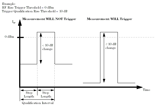
RF Rise: If you choose aTrigger Qualification TypeofRF Rise, then the measurement will not trigger unless the UE's signal rises above theRF Rise Trigger Thresholdvalue AND crosses this level with a positive change in power equal to or greater than the Trigger Qualification Rise Threshold . For example, ifRF Rise Trigger Thresholdis set to0 dBmandTrigger Qualification Rise Thresholdis set to10 dB, then the measurement will not trigger until the UE's signal rises above 0 dBm AND increases in power by at least 10 dB within the qualification interval. The qualification interval is one Step Length before the transition across theRF Rise Trigger Thresholdand oneStep Lengthafter the transition. (The power measurements performed in the qualification interval are performed according to the Measurement Interval , Trigger Delay , and RRC Filter settings, see Specifying the Measurement Characteristics for Each Step ). -
RF Fall: If you choose aTrigger Qualification TypeofRF Fall, then the measurement will not trigger unless the UE's signal rises above theRF Rise Trigger Thresholdvalue AND then exhibits a negative change in power equal to or greater than the Trigger Qualification Fall Threshold during the qualification interval. The qualification interval is the twoStep Lengthsimmediately after the transition across theRF Rise Trigger Threshold. -
RF Rise and Fall: If you choose aTrigger Qualification TypeofRF Rise and Fall, then the measurement will not trigger unless the UE's signal rises above theRF Rise Trigger Thresholdvalue AND crosses this level with a positive change in power equal to or greater than the Trigger Qualification Rise Threshold AND then exhibits a negative change in power equal to or greater than the Trigger Qualification Fall Threshold . In other words, both requirements of aTrigger Qualification TypeofRF RiseandRF Fallas explained above must be met
No matter which type is chosen for the
Trigger Qualification Type, if the requirements are met, then the measurement will trigger at the point at which theRF Rise Trigger Thresholdwas crossed.This setting is only available when Trigger Qualification State is set to
On. -
-
Trigger Qualification Rise Threshold
This setting is only applicable when Trigger Source is set to
RF Rise.This setting specifies the positive change in power that must occur for the measurement to trigger when the
RF Rise Trigger Thresholdis crossed, when Trigger Qualification Type is set toRF RiseorRF Rise and Fall. -
Trigger Qualification Fall Threshold
This setting is only applicable when Trigger Source is set to
RF Rise.This setting specifies the negative change in power that must occur for the measurement to trigger when the
RF Rise Trigger Thresholdis crossed, when Trigger Qualification Type is set toRF FallorRF Rise and Fall.
Other Measurement Parameters
-
34.121 5.7A Measurement Configuration
This setting should be used in conjunction with the 34.121 Preset Call Configurations . The
34.121 5.7A Measurement Configurationsetting sets the following:Trigger Arm=Single,Steps=37,Step Length=333.3 us,Measurement Interval=283.3 us,Trigger Source=HS-DPCCH,HS-DPCCH Trigger Subframe Alignment=subframe 0,Trigger Delay=-308.3 us, andRRC Filter=Off. You can then use the marker to measure the power step changes and ensure that your UE conforms to 5.7A (see Measuring 3GPP TS 34.121 v7.5.0 s5.7A HS-DPCCH ). - Trigger Arm (see Trigger Arm (Single or Continuous) Description )
- Measurement Timeout (see Measurement Timeouts )
Dynamic Power Analysis Measurement Results
- Integrity Indicator (see Integrity Indicator )
-
Number of Steps Measured
You can query the number of steps measured using the FETCh:WDPAnalysis commands. The number of steps measured is also displayed on the front panel graphical display (see How Do I Make a Dynamic Power Analysis Measurement? ).
The number of steps measured is determined by the Steps setting.
-
Average Power for Each Step (in dBm)
Once the dynamic power analysis measurement has autoranged and triggered on the UE's power sequence, the test set then measures the average power for each step in the sequence as specified by the Measurement Interval , Trigger Delay , and RRC Filter settings. (See Specifying the Measurement Characteristics for Each Step .)
You can retrieve the average power measured for each step using the FETCh:WDPAnalysis commands or from the front panel (see How Do I Make a Dynamic Power Analysis Measurement? ).
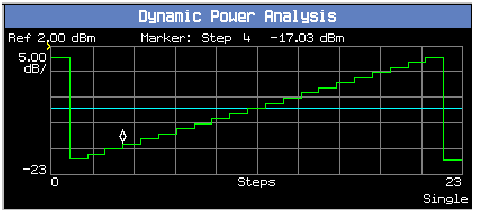
A typical UE power calibration measurement result is shown below:

Dynamic Power Analysis Measurement Input Signal Requirements
The dynamic power analysis measurement can measure power between -61 dBm and +28 dBm.
The dynamic range for any one measurement is 40 dB when
RRC Filter
=
On
(the UE's power may not vary by more than 40 dB in a single power sequence).
Dynamic Power Analysis Measurement Calibration
You must calibrate the dynamic power analysis measurement using the
Calibrate Measurements
procedure (see
Calibrating the Test Set
).
Related Topics
Manual Operation: How Do I Make a Dynamic Power Analysis Measurement?
Programming the Dynamic Power Analysis Measurement
Dynamic Power Analysis Troubleshooting
What 3GPP W-CDMA/HSPA Conformance Tests Are Supported?
Product Note: W-CDMA Dynamic Power Analysis Using the Keysight 8960 Wireless Communications Test Set


