1. Use a Torque Wrench
Electrical Connector Care
Damage to electrical input connectors (as well as connectors on calibration and verification devices, test ports, cables, and other devices) can degrade measurement accuracy and damage instruments. Replacing a damaged electrical connectors can cost thousands of dollars, not to mention lost time! This expense can be avoided by observing the important precautions described in the topics referenced below.
The input circuits can be damaged by electrostatic discharge (ESD). Avoid applying static discharges to the front-panel input connectors. Before connecting any coaxial cable to the connectors, momentarily short the center and outer conductors of the cable together. Avoid touching the front-panel input connectors without first touching the frame of the instrument. Be sure the instrument is properly earth-grounded to prevent buildup of static charge.
Do not twist one connector into the other (like inserting a light bulb). This happens if you turn the device body rather than the connector nut. Major damage to the center conductor can occur if the device body is twisted. Use open-ended wrenches on wrench flats on the outer bodies of the connector to help restrict rotation.
Apply force perpendicular to the wrench handle. This applies torque to the connection through the wrench. Do not hold the wrench so tightly that you push the handle straight down along its length rather than pivoting it, otherwise you apply an unlimited amount of torque.
The connector savers shown in the following table are useful in prolonging instrument life and ensuring better quality measurements.
| Connector | Part Number | Comments |
|---|---|---|
| 3.5 mm | 85052-60013 | Metrology grade |
| 3.5 mm | 85059C | Instrument grade |
| 2.92 mm | 11904 | 2.4 to 2.92 adapters |
| 2.4 mm | 85056-60007 | Metrology grade |
| 1.85 mm | 85058-60009 | Instrument grade |
| 1.0 mm | Y1901B | 1.0 mm to 1.85 mm adapter |
| 1.0 mm | Y1903B | 1.0 mm to 2.92 mm adapter |
Coaxial Connector Types
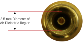
The following table shows commonly used RF coaxial connectors. With the exception of the SMA connector, connector types are identified by the diameter (in millimeters) of the air dielectric region as shown in this picture of a 3.5 mm connector.
| Connectory Type | Frequency Range | Coupling Torque | Compatible Connectors | Notes |
|---|---|---|---|---|
1.0 mm Connector |
≤ 110 GHz | 0.45 Nm (4 lb-in) |
1.0 mm | The smallest connector and is used on the N1060A Precision Waveform Analyzer module. This connector requires extra care to prevent expensive repairs and repair downtime when making connections. |
1.85 mm Connector |
≤ 70 GHz | 0.57 Nm (5 lb-in) |
2.4 mm | 1.85 mm and 2.4 mm connectors are intermateable. To aid identification, 1.85 mm Keysight connectors have a groove in the male nut and female shoulder. The outer thread size of 1.85 mm and 2.4 connectors is larger than the tread size on SMA, 2.92 mm, and 3.5 mm connectors. This makes the area of the outer conductor's mating surface appear very large compared to the relatively smaller air dielectric. |
2.4 mm Connector |
≤ 50 GHz | 0.9 Nm (8 lb-in) |
1.85 mm | |
2.92 mm Connector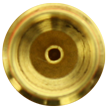 |
≤ 40 GHz | 0.9 Nm (8 lb-in) |
3.5 mm and SMA | 2.92 mm, 3.5 mm, and SMA connectors are intermateable. 2.92 mm and 3.5 mm connectors use the same center pin. Inserting the larger SMA (m) center pin into a 2.92 mm or 3.5 mm connector can slightly degrade the connector. It is recommended that you only mate SMA (m) connectors to other connectors that you reserve for this purpose. SMA connectors use a Teflon delectric. |
3.5 mm Connector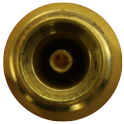 |
≤ 34 GHz | 0.9 Nm (8 lb-in) |
2.92 mm and SMA | |
SMA Connector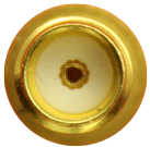 |
≤ 24 GHz | 0.9 Nm (8 lb-in) |
2.92 mm and 3.5 mm |
Making RF Connections
- Work at a static-safe workstation.
- Visually inspect the connectors. If necessary, clean the connectors. Carefully align the connectors. The male connector center pin must slip concentrically into the contact fingers of the female connector.
- Push the connectors straight together.
- Tighten lightly using only your fingers as, at this point, all you want is a connection in which the outer conductors make gentle contact at all points on both mating surfaces. Very light finger pressure (no more than 2 pound-inches of torque) is enough.
Do not twist one connector into the other (like inserting a light bulb). This happens if you turn the device body rather than the connector nut. Major damage to the center conductor can occur if the device body is twisted.
- Use a torque wrench to make the final connection. This guarantees perfectly tight, consistent connections that prevents connector damage. Refer to Applying Torque for the proper handling of the wrenches and to view the correct connector “flats” on which to position the wrenches.
The maximum torque setting is 4 in-lb (0.45 Nm) for 1.0 mm connectors.
Rotate only the connector nut when you make the connection. Do not rotate the cable or adapter.
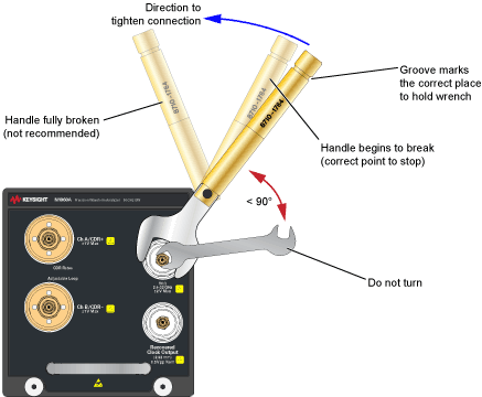
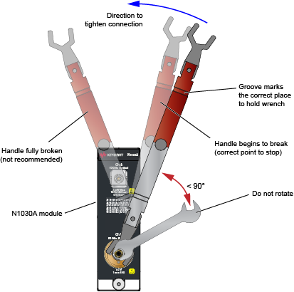
Hold the torque wrench lightly at the groove located at the end of the handle.
Apply force perpendicular to the wrench handle. This applies torque to the connection through the wrench. Do not hold the wrench so tightly that you push the handle straight down along its length rather than pivoting it, otherwise you apply an unlimited amount of torque.
Tighten the connection just to the torque wrench "break" point as shown in Wrenches Positioned on Correct Flats. Do not tighten the connection further.
The following are torque techniques recommended for various electrical modules which may be used with the N1000A mainframe. These techniques can be used for electrical connectors in general.
Channel Input Connectors
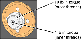
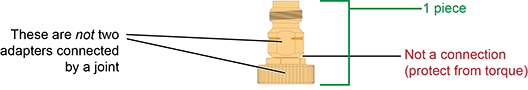
On several DCA-X modules and DCA-M modules, a front-panel 1 mm Channel Input connector is used as shown in this picture. These 1 mm connectors have both outer in inner threads that require different torque specifications. Always use the correct torque specification as noted when making connection to the Channel Input. Damage to the Channel Input connector results in an expensive repair and extended down time while the module is being repaired.
Channel Input Y1901/3B Adapters
The following picture show the two types of ruggedized 1mm adapters, which are supplied in the N1030A and N1060A accessory kits:
- 1 mm to 1.85 mm Y1901B adapter
- 1 mm to 2.92 mm Y1903B adapter
These adapters are designed to be installed on the front-panel channel inputs. It is recommended that you always use them. Due to the physical requirements needed to obtain high performance, the geometry of these, as well as all, 1 mm connectors, demands special care to avoid expensive damage as explained in this document.
Although not supplied in the kit, a 1 mm-to-1 mm Y1900B adapter is available to purchase from Keysight Technologies.
Applying Torque
For the 1 mm Channel Input connector, use the dual torque wrench shown in the Wrenches on Channel Input.
The silver end of the dual torque wrench is 4 lb-in. The red end of the torque wrench is 10 lb-in.
Selecting and Positioning the Wrenches
The following figures show the proper “flats” on which to place the wrenches for several possible connections.
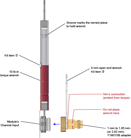
Y1901/3B Adapter to Channel Input
This figure show the correct placement of the 10 lb-in dual torque wrench (the red end) and the 8 mm open end wrench. On the Y1901/3B adapter, connect the 8 mm wrench on the flats that are adjacent to the knurled ring as shown in this figure.
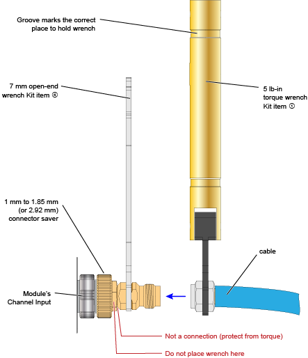
Cable or Adapter to Y1901/3B Adapter
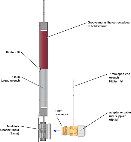
This figure show the correct placement of the 5 lb-in torque wrench and the 7 mm open end wrench for connecting a cable, adapter, or other item to the Y1901/3B adapter.
Adapter to Channel Input (without Y1901/3B)
It is recommended that you always connect an Y1901/3B adapter to the 1mm channel input. However, if you want to connect an adapter or cable directly to a channel input connector, use the 4 lb-in end of the dual torque wrench (silver end of the dual torque wrench). Do not use the red end of the dual torque wrench which is only used when connecting the stronger outside channel-input connector threads to the Y1901/3B connector.
Never apply in excess of 4 lb-in of torque to the 1mm channel input’s inner threads. Confirm also that your adapter or channel connector can withstand 4 lb-in.
For 2.92 mm connectors the maximum torque setting is 8 in-lb (0.9 Nm).
The following drawings illustrate proper connection handling techniques for the following front-panel connectors:
- N1000A's 2.92 mm Trigger and Precision Timebase Inputs.
- N1060A’s Precision Timebase and Recovered Clock 2.92 mm connectors.
For these connections, the 8 lb-in (0.9 Nm) torque wrench is used (accessory kit item 2). The following drawing shows the wrench positions for connecting a 2.92 mm-to-2.92 mm adapter to the N1000A's front-panel Recovered Clock output or Precision Timebase input.
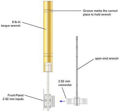
Once the wrenches are properly positioned, the following drawing shows how to use the wrenches to torque the connection. Although the drawing shows an N1060A's front panel, the technique used is identical when making connections to the N1000A's 2.92 mm connectors.