IGBT: Diode Ir-Vr Test
Measures the reverse bias voltage vs. current characteristics of the body (free-wheeling) diode.
Used with:
-
B1506A: IGBT DUT
- B1505A: IGBT DUT, IV test type
- If the data sheet lists a maximum test limit for a parameter, use that value.
- If there is no maximum test limit, use a typical value.
See also Setting IV and CV Test Parameters.
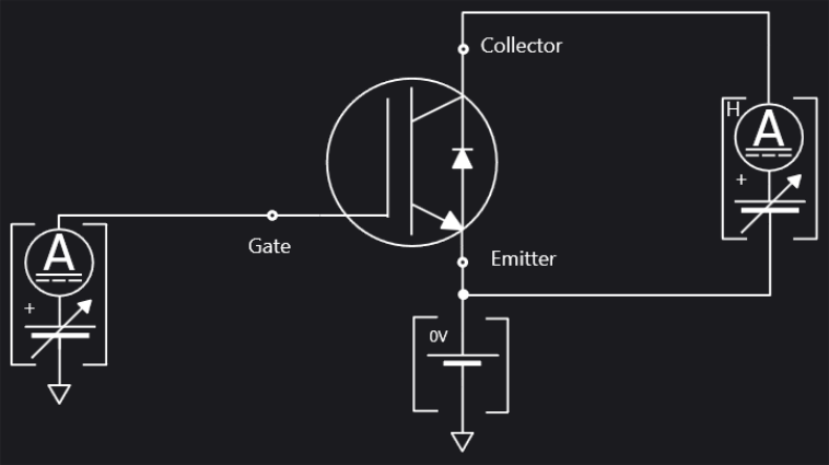
Test Schematic
Gate Parameters
Click here for detailed information about each item in the list.
IntegTime: Use the drop-down menu to select the integration time for one measurement point; either Short (default), Medium, or Long.
Gate: The SMU connected to Gate terminal, primary sweep voltage output. Select Gate SMU from the drop-down menu.
Vc@Ices (V): The Collector voltage to decide Collector-Emitter cutoff current Ices.
Ic@BVces (A): The Collector current to decide Collector-Emitter breakdown voltage BVces.
Vg (V): The Gate voltage.
Emitter: The GNDU:GND connected to Emitter terminal. This field cannot be changed.
Collector Parameters
Click here for detailed information about each item in the list.
Collector: The SMU connected to Collector terminal, secondary sweep voltage output. In general, use the Input HVSMU for this test.
VcStart (V): The Sweep start voltage for Collector terminal.
VcStop (V): The Sweep stop voltage for Collector terminal.
VcStep (V): The Sweep step voltage for Collector terminal.
IcLimit (A): The Collector current compliance.
IgMinRange (A): Use the drop-down menu to select the minimum range for the gate current measurement.
