IGBT: Ic-Vce Test
Measures Ic-Vce characteristics for 3-terminal IGBT devices. SMU pulse is used for the Collector-Emitter voltage output. The sweep scale is always linear.
Used with:
-
B1506A: IGBT DUT
- B1505A: IGBT DUT, IV test type
- If the data sheet lists a maximum test limit for a parameter, use that value.
- If there is no maximum test limit, use a typical value.
See also Setting IV and CV Test Parameters.
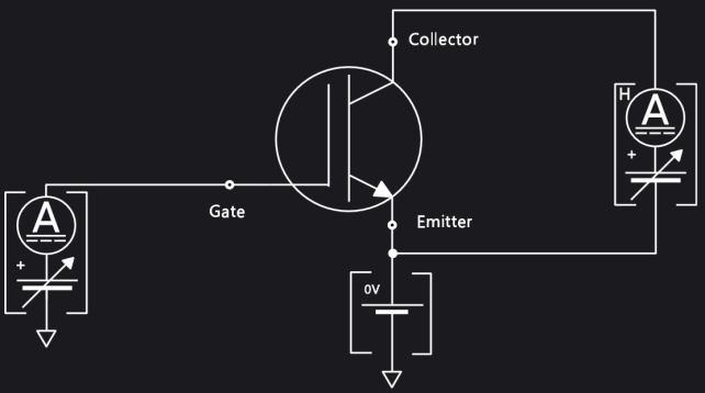
Test Schematic
Gate Parameters
Click here for information about each item in the list.
Gate: The SMU connection to Gate terminal, secondary sweep voltage output. Select Gate SMU from the drop-down menu.
VgStart (V): The DC bias sweep start voltage (in Volts).
VgStop (V): The DC bias sweep stop voltage (in Volts).
VgStep (V): The bias sweep step voltage (in Volts).
Emitter: The GNDU:GND connected to Emitter terminal. (This parameter cannot be changed.)
Gate Resistance: Specify the desired Gate Resistance for the device, either 0 (default), 10, 100, or 1000 W.You must set the same Gate Resistance value in two places: 1) in the parameters for this test; and 2) in the EasyEXPERT software for your B1505A or B1506A power analyzer. See Additional IV and CV Test Information.
Collector Parameters
Click here for information about each item in the list.
Collector: The type of SMU connected to Collector terminal, primary sweep voltage output. Use the drop-down menu to select UHCU or HCSMU.
VcStart (V): The Sweep start voltage for Collector terminal.
VcStop (V): The Sweep stop voltage for Collector terminal.
VcLinearStep (V): The Sweep step voltage for Linear SweepOutput for the Collector terminal.
IcLimit (A): The Collector current compliance.
PcLimit (W): The Collector power compliance (in Watts).
VcLimit (V): The Collector power compliance (in Volts).
PulsePeriodMode: The Pulse period mode, AUTO or MANUAL. (If you choose MANUAL, you must also set the ManualPulsePeriod parameter.)
ManualPulsePeriod (s): The Pulse period. Use this parameter only when you have selected PulsePeriodMode = MANUAL.
PulseWidth (s): The Pulse width.
Example
This example uses a discrete IGBT as the test device.
This device has the following basic characteristics.
- VCES: 330 V
- VGES: +/-30 V
- IC: 180 A(DC), 450 A(Pulse)
Test Setup
-
Select IGBT as the device type in the Select DUT drop-down menu.
-
Select the Ic-Vce checkbox.
-
Use the Ic-Vce chart of the datasheet to set the gate start, stop, and step voltages.
-
For Collector, select UHCU.
-
Set the Collector sweep stop voltage as 30 V. (This value is the stop voltage of the internal voltage source of the UHCU, not the stop voltage of the sweep at the device terminal.)
-
Set 200A as a compliance current. It limits the current flowing into the device at the upper limit of the vertical scale.
-
Set 6 V as the voltage compliance. This value is used to stop the sweep.
-
Click the Measurement button to start the measurement.
How to determine the stop voltage
The voltage actually applied to the device is determined by the setting voltage, output current, and the voltage at the device terminal due to a load line effect of the UHCU.
From the IC-VCE characteristics of the datasheet, the maximum voltage and current point is the right upper corner of the chart, 200 A and 6 V. To draw the IV chart in the whole area, the maximum setting voltage of the UHVU becomes: 6 + 200 A x 120 mΩ = 30 V.
