FET: Id-Vds Test
Measures Drain current vs. Drain voltage characteristics (Id-Vds with multiple Vg steps) for MOSFET or GaN FET. SMU pulse is used for the Drain-Source voltage output.
Used with:
-
B1506A: FET DUT
- B1505A: FET DUT, IV test type
- Instrument option in the Hardware Configuration dialog.
- If the data sheet lists a maximum test limit for a parameter, use that value.
- If there is no maximum test limit, use a typical value.
See also Setting IV and CV Test Parameters.
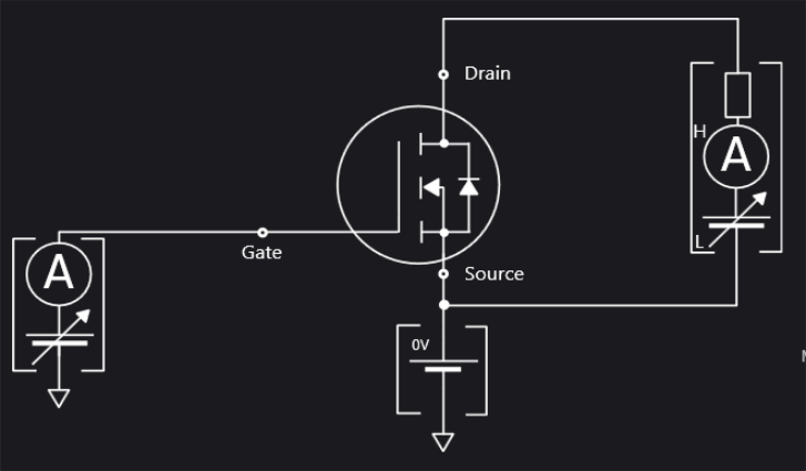
Test Schematic
Gate Parameters
Click here for detailed information about each item in the list.
Gate: The SMU connected to Gate terminal, primary sweep voltage output. Select Gate SMU from the drop-down menu.
VgStart (V): The Sweep start voltage for Gate terminal.
VgStop (V): The Sweep stop voltage for Gate terminal.
VgStep (V): The Sweep step voltage for Gate terminal.
Source: The GNDU:GND connected to Source terminal. This field cannot be changed.
Drain Parameters
Click here for detailed information about each item in the list.
Drain: The SMU connected to Drain terminal, secondary sweep voltage output.
VdStart (V): The Sweep start voltage for Drain terminal.
VdStop (V): The Sweep stop voltage for Drain terminal.
VdLinearStep (V): The Sweep step voltage for Drain terminal, effective if Scale=LINEAR.
IdLimit (A): The Drain current compliance.
PdLimit (W): The Drain power compliance.
PulsePeriodMode: The Pulse period mode, AUTO or MANUAL. (If you choose MANUAL, you must also set the ManualPulsePeriod parameter.)
ManualPulsePeriod (s): The Pulse period. Use this parameter only when you have selected PulsePeriodMode = MANUAL.
PulseWidth (s): The Pulse width.
Gate Resistance: Gate Resistance: Specify the desired Gate Resistance for the device, either 0 (default), 10, 100, or 1000 W.You must set the same Gate Resistance value in two places: 1) in the parameters for this test; and 2) in the EasyEXPERT software for your B1505A or B1506A power analyzer. See Additional IV and CV Test Information.
Example
In this example, discrete power FET is used as the example test device.
This device has the following basic characteristics.
- VDSS: 40 V
- IDM: 350 A(DC), 1390 A(Pulse)
- RDS(on): Typ. 1.35 mΩ
ID-VDS setup:
Follow the next steps to set up ID-VDS of FET.
-
Select FET as device type.
-
Select the Id-Vds checkbox.
-
Create a gate step voltage list based on the Ic-Vce chart of the data sheet. For example, 4.5, 5, 5.5, 6... volts.
-
Set Vd stop voltage as 60 V. This value is the stop voltage of the internal voltage source of the UHCU, not the stop voltage of the sweep at the device terminal.
The ideal stop voltage is calculated as:
Stop V (ideal) = 120 mΩ x 500 A + 10 V = 70 V,
but the maximum output voltage of UHCU is limited to 60 V.
Therefore, set maximum 60 V here. -
Set 500 A as the Drain compliance current. It limits the current flowing into the device at the upper limit of the vertical scale.
-
Set 10 V as the voltage compliance. This value is used to stop the sweep at the edge of the horizontal axis.
-
Set the drain Pulse Width to 100 μs.
-
Click the Start button.
