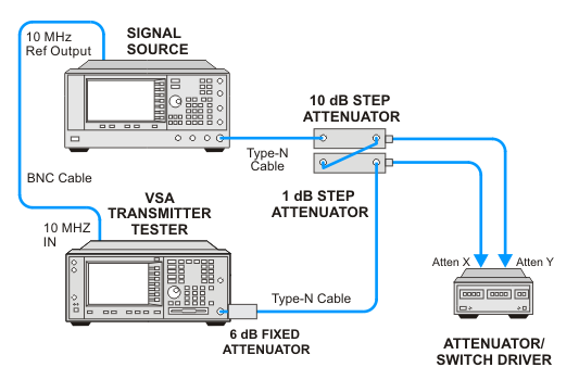
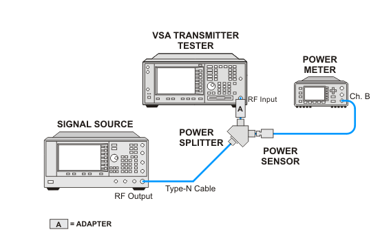
This test is extremely sensitive to mismatch uncertainties. Use extra care in making equipment connections. Verify that all connectors are tight. In addition, ensure that the fixed attenuator is connected directly to the VSA.
|
|
This test is extremely sensitive to mismatch uncertainties. Use extra care in making equipment connections. Verify that all connectors are tight. In addition, ensure that the fixed attenuator is connected directly to the VSA. |
There are no direct measurements for this test. The Absolute Amplitude test combines the amplitude verses frequency data taken in Frequency Response adjustment with the amplitude test data taken in Amplitude Accuracy at 50 MHz. The measured errors for the two tests are added together to create the Absolute Amplitude Error.
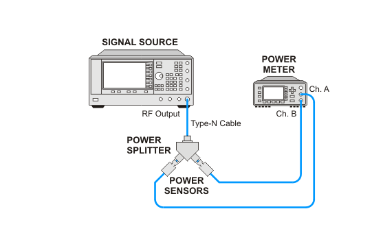
The Frequency Response Adjustment test measures amplitude error as a function of frequency. It measures the amplitude of the input signal at points in a range from 7 MHz to 4 GHz. The measured signal amplitude is compared to the amplitude of the signal as measured by a calibrated power meter. The difference between the two measurements is the amplitude error and is normalized to 50 MHz. The test has three parts: Power Splitter Characterization, Flatness Measurement at 7 MHz to 50 MHz, and Flatness Measurement at 50 MHz to 4 GHz.
Power Splitter Characterization increases the accuracy of the measurement by measuring the amplitude difference between the two arms of the splitter. The amplitude difference is used as a correction factor for the flatness calculation.
The 7 MHz to 50 MHz Flatness Measurement and the 50 MHz to 4 GHz Flatness Measurement parts of the test measure the amplitude of the source at various frequencies and calculate the flatness of the response. A flatness report is generated that is critical for troubleshooting Absolute Amplitude Accuracy failures.
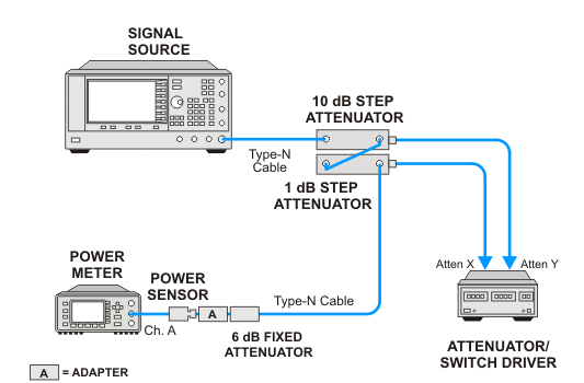
The Amplitude Accuracy at 50 MHz test measures the amplitude accuracy of the instrument at a fixed frequency. The signal source is provided by a signal generator tuned to 50 MHz. The source amplitude is adjusted to 3 levels for each of the three parts of the test. At each adjustment, the source level is measured through external precision step attenuators, set at 0 dB, with a power meter.
In the first two parts of the test, the attenuators are set to various levels for each test point. The amplitude of the source signal is measured by the power meter at the 0 dB attenuator setting, and the attenuator settings at each test point are used to calculate the input signal level. The level measured by the VSA and the calculated input level are used to calculate the amplitude accuracy error.
In the third part of the test, the source and step attenuators are set, and remain unchanged throughout the remainder of the test. However, the input attenuation is set to three different levels. As with the first two parts of the test, the input level and the measured values are used to calculate the amplitude accuracy error.
Click here for troubleshooting.
Related adjustments:
|
Test Equipment |
Recommended Model Number |
|---|---|
|
RF Source 1 |
E8257D |
|
RF Source 2 |
|
|
Power meter |
N1914A |
|
Power sensor |
N8482A |
|
Power splitter |
11667A |
|
10 dB step attenuator |
8496G Option 001, H50 |
|
1 dB step attenuator |
8494G Option 001, H50 |
|
6 dB fixed attenuator |
8491A Option 006 |
|
Attenuator driver |
11713B |
|
Attenuator interconnector kit |
11716A |
|
Cable, Type-N |
11500C |
|
Cable, BNC |
8120-2582 |
|
Adapter, Type-N (m) to Type-N (m) |
1250-1475 |
|
Adapter, Type-N (f) to Type-N (f) |
1250-1472 |
|
|
The second part of the Absolute Amplitude test is a test of the amplitude accuracy. This test of amplitude accuracy is repeated three times which means that you will have to connect and disconnect your test setup several times |