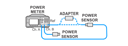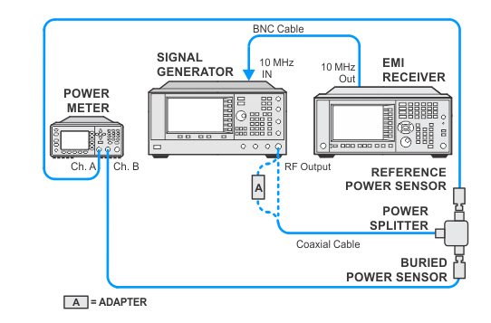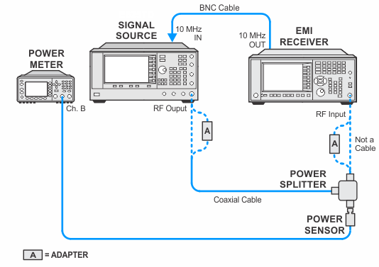
Frequency response (aka. Flatness) is defined as the amplitude deviation from the reference amplitude at 50 MHz. The complete EMI receiver frequency response is measured with several tests. The model and options of the DUT will determine which tests are run from the list below:
A “buried power sensor” technique is used to characterize the tracking error of a power splitter in order to avoid the relatively large specified tracking error. This technique reduces the measurement uncertainty to verify the frequency response specification for the 3.6 GHz to 44 GHz range. The buried sensor calibration is valid for eight hours.
This test determines the relative frequency response over the frequency range from 3.6 GHz to 44 GHz.
Click here for troubleshooting.
|
Test Equipment |
Model Number1 |
|---|---|
|
Microwave Signal Generator #1 |
PSG Models |
|
Power Meter |
N1914A |
|
Microwave Power Sensor
|
N8485A CFT |
|
Microwave Power Splitter
|
11667B |
|
Millimeter Power Sensor
|
N8487A CFT |
|
Millimeter Power Splitter
|
11667C |
|
Cable, BNC |
8120-1840 |
|
Cable, coaxial 3.5 mm
|
11500E |
|
Cable, coaxial 2.4 mm
|
8120-6164 |
|
Adapter, Type-N (m) to 3.5 mm (m)
|
1250-1743 |
|
Adapter, 3.5 mm (f) to 3.5 mm (f)
|
83059B |
|
Adapter, 2.4 mm (f) to 3.5 mm (f)
|
11901B |
|
Adapter, 3.5 mm (f) to Type-N (m)
|
08485-60005 |
|
Adapter, 2.4 mm (f) to Type-N (m)
|
08487-60001 |
|


