Q-P Detector Absolute Calibration Performance Test
This test compares the amplitude of a 60 dBuv CW signal to the amplitude
of a pulsed signal in Quasi-Peak Detection mode.
The measurements are performed with pulsed signals set to the reference
PRF rates of 25 Hz (Band A), or 100 Hz (Bands B, C, and D). This test
measures three frequencies: 100 kHz (Band A), 10 MHz (Band B), and 100
MHz (Band C). Band D is not tested due to limitations in the DC Pulse
Generator.
Test Solutions
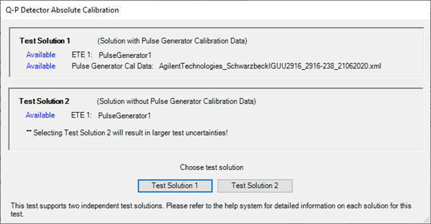
There are two test solutions available depending on the existence of the pulse generator calibration data. At the start of the test, TME will detect if there is existing calibration data for the pulse generator. If there is calibration data, it will show as Available in Test Solution 1 as shown in the image below. To use Test Solution 1, the user will first need to run the Pulse Generator Calibration Data Editor Utility which will enter the pulse generator's amplitude corrections and calibration uncertainties from the calibration report/certificate. Test Solution 1 is the preferred solution as explained in the next section.
If there is no calibration data detected for the pulse generator, select Test Solution 2 in the dialog and continue with the test.
TME dialog
Test Solution 1 is the preferred solution
Although either solution can be selected if the calibration data is detected, it is strongly recommended to choose Test Solution 1 and run the Pulse Generator Calibration Data Editor Utility. This solution will use characterized data and uncertainties which will give better margins and lower test uncertainties.
In Test Solution 2, the pulse generator specifications will be used in the uncertainty calculations which will yield greater uncertainty numbers.
Sine Wave Generator Setups
The N7818A E.10.00 release introduced the Schwarzbeck IGUU 2918 as the recommended pulse generator. The Schwarzbeck IGUU 2916 is discontinued but will be supported as the alternative model. The difference in the two models is that the IGUU 2918 model does not have a built-in sine wave generator. To accommodate for this difference, the test will now use a PSG signal generator as the sine wave generator. This signal generator solution will be used with both pulse generator models: the IGUU 2918 model and the discontinued IGUU 2916 model. The setup in previous releases using the sine wave generator in the IGUU 2916 pulse generator will no longer be supported.
Troubleshooting
You may get an GPIB connection error when using the IGUU 2918.
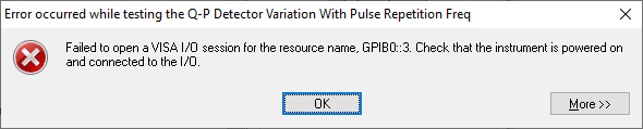
There is a known issue with certain versions of the Keysight IO Library not recognizing the Schwarzbeck IGUU 2918 pulse generator and therefore causing a GPIB connection failure. There are two work-around methods to correct this error. Refer to the Connecting GPIB Instruments section of Getting Started for more information.
For other troubleshooting tips for this test, click here.
Required Test Equipment
|
Test Equipment
|
Recommended Model Number
|
Alternative Model Number
|
|
CISPR Pulse Generator1
|
Schwarzbeck IGUU 2918
|
Schwarzbeck IGUU 2916
|
|
Microwave Signal Generator #1
|
PSG Models
(see equipment list)
|
|
|
Attenuator, fixed 20 dB
|
8491A Option 020
|
8491B Option 020
|
|
Power Meter
|
N1914A
|
N1912A
E4419B
E4419A
|
|
Power Sensor
|
E9304A Option H18
|
|
|
Cable, Type-N
|
11500C
|
|
|
Cable, BNC
|
8120-1840
|
8120-2582
10503A
|
|
Adapter, Type-N (f) to 3.5 mm (f)
- For Option C35
- For 3.5 mm source
|
1250-1745
|
|
|
Adapter, Type-N (f) to 2.4 mm (f)
- For Option 544
- For 2.4 mm source
|
11903B
|
|
Connection Setups
Click on the links below for images depending on the pulse generator model being used.
Click here for Schwarzbeck IGUU 2918.
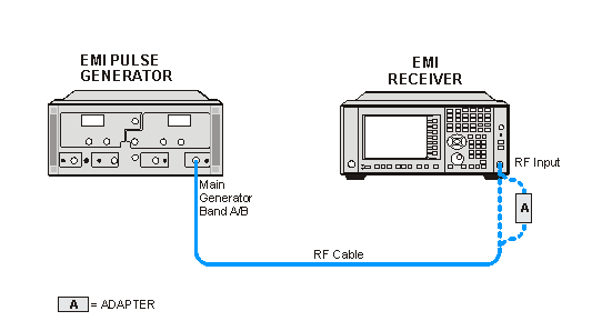
Q-P Detector Reference Measurement Bands A/B Setup
Schwarzbeck Pulse Generator IGUU 2918
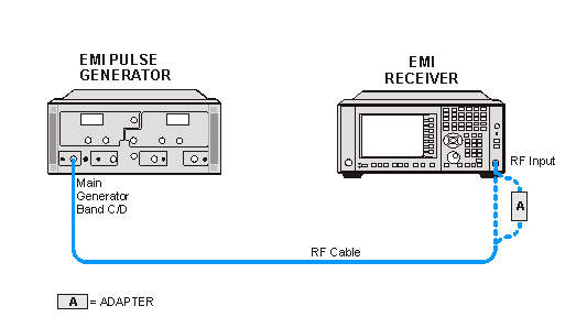
Q-P Detector Reference Measurement Bands C/D Setup
Schwarzbeck Pulse Generator IGUU 2918
Power Meter Calibration

CW Power Measurement Setup
Q-P Detector CW Measurement Setup
Click here for Schwarzbeck IGUU 2916.
Q-P Detector Reference Measurement Bands A/B Setup
Schwarzbeck Pulse Generator IGUU 2916
Q-P Detector Reference Measurement Bands C/D Setup
Schwarzbeck Pulse Generator IGUU 2916
Power Meter Calibration
|

|
The setup using the sine wave generator in the IGUU 2916 is no longer supported. That connection will now be made using a PSG signal generator. See Sine Wave Generator Setups above for more information.
|
CW Power Measurement Setup
Q-P Detector CW Measurement Setup
