- N995xA: Both ports are tested.
- N996xA: Only test Port 1.
- This adjustment requires Option CFG. Refer to the CFG Option topic for more information.
- The Source Power adjustment should always be followed by the Error Terms adjustment.
N9960A/61A/62A
|
|
|
The NA source power adjustment is divided into two parts. The first part of the adjustment generates amplitude corrections versus frequency for a fixed output level setting. This is essentially a source flatness adjustment. The second part of the adjustment generates amplitude corrections versus output level setting (i.e. power step accuracy). This part of the adjustment corrects for the non-linear behavior of the output DAC. The algorithm essentially generates the coefficients of a fourth order polynomial that describes the amplitude versus DAC setting.
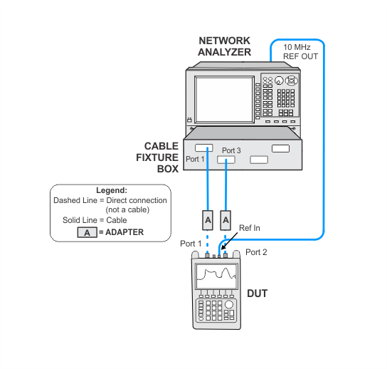
This adjustment uses two equipment setups. A power meter will be used to test frequencies below 10 MHz. A network analyzer will be used to test frequencies above 10 MHz. The network analyzer will need to be calibrated prior to running the adjustment. Refer to the Network Analyzer Calibration Procedure for Adjustments for more information.
|
Related test: |
|
|
The network analyzer used in this adjustment must be calibrated prior to running the adjustment. The calibration will need to be repeated once every three days or if the connectors or cables have been disturbed. If it's been within the three day time frame and the connectors and cables have not been disturbed, then the network analyzer calibration is not necessary and you may proceed with the adjustment. For a list of required equipment and calibration instructions to perform the network analyzer calibration, go to the Network Analyzer Calibration Procedure topic page. |
|
Test Equipment |
Recommended Model Number1 |
|---|---|
|
Network analyzer |
N5247B with options:
|
|
Power meter |
N1914A |
|
Power sensor1 |
E9304A Opt H20 |
|
Power sensor cable |
11730A |
|
Cable, 1.85 mm (f) to 1.85 mm (m)
|
JUNFLON J12J102905-00-2 |
|
Cable, BNC (m) to BNC (m) |
8120-2582 |
|
Adapter, 2.4 mm (f) to 2.4 mm (f)
|
11900B |
|
|
|
The following notes apply to illustrations in the FieldFox Help:
|