Enable Matrix Decoder (802.16 OFDMA)
: Cleared (See OFDMA Standard Presets Table.)
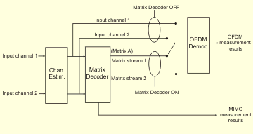
enables the Matrix Decoder functionality. When is selected, the parameter can be used to select which matrix data stream to analyze.
The VSA OFDMA Matrix decoder is not an ideal decoder and approximates the behavior of a receiver’s Matrix decoding algorithm. Therefore ithe resultant RCE Relative Constellation Error is the RMS level of the Error Vector Magnitude, averaged over all subcarriers and all detected OFDM symbols. metrics from the Matrix Decoder will not match the performance of an ideal implementation of a Matrix A or Matrix B decoder under all channel models or impairments and may show significant variance. The RCE results from the enabled measurement should be considered qualitative as a validation of the basic MIMO Multiple Input, Multiple Output: A physical layer (PHY) configuration in which both transmitter and receiver use multiple antennas. encoding implemented by the transmitter. A traditional BER Bit Error Ratio - A ratio of the number of errors to data bits received on a digital circuit. test with use of channel emulation and an ideal Matrix decoder implementation should be used to fully validate the coding performance of the MIMO transmitter.
The and parameters are only available when a mutiple antenna STC Space Time Coding (STC) allows the transmitter to transmit signals (information) both in time and space, meaning the information is transmitted by two antennas at two different times consecutively. zone type is specified (STC type is specified on the Downlink Zone Definition Editor.)
Using the Matrix Decoder
When demodulating a Downlink zone which uses Matrix A or Matrix B coding, the training mode ( tab > Pilot Tracking) is not valid when the matrix decoder is disabled (cleared). This is because the data subcarriers may not be valid due to coupling between transmitters. In this situation, the VSA will use training mode instead
When operating as a single channel VSA, the VSA expects a signal of Antenna-0 format on input channel 1. If energy from Antenna-1 is present on this input (due to hardware leakage or crosstalk), this energy is analyzed as uncorrelated noise and is included in the EVM Error vector magnitude (EVM): A quality metric in digital communication systems. See the EVM metric in the Error Summary Table topic in each demodulator for more information on how EVM is calculated for that modulation format. result. Demodulating the Antenna-1 format requires a dual-channel analyzer.
When operating as a dual channel VSA, the VSA expects two signals, corresponding to the Antenna-0 and Antenna-1 formats, on inputs 1 and 2 respectively. As in the single-channel setup, leakage between the signals is analyzed as noise, and is included in the RCE.
When the Matrix Decoder is selected, the VSA performs the matrix math to separate the two transmit streams. The resulting displays of RF Radio Frequency: A generic term for radio-based technologies, operating between the Low Frequency range (30k Hz) and the Extra High Frequency range (300 GHz). metrics, data bits, etc. are those of the original waveform(s), prior to encoding and PRBS Pseudo-Random Binary Sequence rotation. Matrix A (MISO) signals may be measured with either single or dual-channel hardware, while Matrix B (MIMO) signals require dual input channels.
See Also