Component Carriers (Flex Frame)
The Component Carriers parameter group configures a table containing the component carriers available to be included in the aggregate signal.
selects whether the reference frequency of the component carriers is defined manually or is the center of the measurement channel. The reference frequency is a base frequency that is used with each component carrier's Offset value to determine the carrier's absolute center frequency
- Meas. Center - The manual Reference Frequency setting is ignored and the referenced frequency is instead defined to be the center of the measurement channel assigned to the component carrier.
- Manual - The reference frequency of a component carrier is manually specified by the Reference Frequency parameter.
Default: Meas. Center
Choices: Meas. Center, Manual
, when Reference Frequency Mode is set to Manual, sets a base frequency that is used with each component carrier's Offset value to determine the carrier's absolute center frequency (Absolute Center = Reference Frequency + Offset).
Default: 0 Hz
includes or excludes the component carrier in the aggregate signal.
Default: Enabled (checked)
Choices: Enabled, disabled
displays the automatically assigned component carrier name, "CCn," beginning with CC0 and incrementing by one for each new CC.
Default: CC0
sets/displays the center frequency for the component carrier. Absolute Center is calculated as the sum of the Reference Frequency and the carrier’s Offset value. Since a component carrier's Absolute Center setting is coupled with the Offset setting, changing one setting will change the other setting accordingly.
sets the frequency offset for the selected carrier. The frequency offset is relative to the measurement's Reference Frequency and is used in calculating Absolute Center value. Since Freq. Offset is coupled with Carrier Center, changing one setting will change the other setting accordingly.
Default: 1 GHz Gigahertz: A frequency measurement which equals one billion hertz.
displays the component carrier's symbol rate (Frame Definition tab > Symbol Rate).
Default: 1 GHz
displays the channels that have been assigned to the component carrier (that contain the transmission of the component carrier). Only one channel can be assigned to a component carrier. You can make this assignment in the Acquisition Configuration editor.
Default: None
 creates a duplicate of a component carrier with all settings identical, including Absolute Center, Offset, Symbol Rate and Assigned Channels.
 deletes a carrier from the Component Carriers table.
adds a new carrier to the bottom of the Component Carriers table. The initial values are set to defaults. A newly added carrier is included in the aggregate signal (enabled) by default.
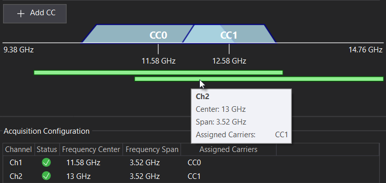
provides a generalized preview of the aggregate signal's channels (in green) and assigned component carriers (in blue). The elements of the diagram are not to scale. Hover over an element for details.
See Also