Basic Tab: Downlink Control Channel Properties (LTE)
Menu Path:
In the dialog's tab, you can set the parameter for P-SS Primary Synchronization Signal, S-SS Secondary Synchronization Signal, PBCH Physical Broadcast Channel, PCFICH Physical Control Format Indicator Channel, C-RS Cell-specific RS, PDCCH Physical Downlink Control Channel, and PHICH Physical Hybrid ARQ Indicator Channel. There are also several other PDCCH and PHICH parameters.
Power Boost
The parameter specifies the expected average subcarrier power of a channel. When there are multiple C-RS antenna ports, the value is split equally over all the C-RS antenna ports.
For example, PBCH is set to 0 dB. When the signal contains a single C-RS antenna port, the expected average subcarrier power of PBCH would be 0 dB, but when there are two C-RS antenna ports, the expected average subcarrier power of PBCH per antenna port would be -3 dB. This is done so that specifying a channel's parameter is like specifying the average power of the channel being transmitted from the base station, regardless of the number of transmit antennas.
When P-SS/S-SS Antenna Port is set to , the P-SS/S-SS parameter specifies the expected average subcarrier power of P-SS/S-SS on the specified antenna port (in other words, the value is not split across all antenna ports). However, when is set to , then the value is split across all antenna ports like the other channels.
Other power boost parameters are expressed relative to the 0 dB level set by C-RS . A value of 2.5 dB for C-RS specifies that the 0 dB level is set to be 2.5 dB below the measured C-RS power level.
For example, setting PBCH to 0.5 dB for a single-antenna signal when C-RS is set to 2.5 dB tells the demodulator to expect the PBCH power level to be 0.5 dB above the 0 dB level (which is 2.0 dB below the measured C-RS power level).
- When selected, the LTE Long Term Evolution demodulator will detect arbitrary power levels for all channels on the tab. C-RS power is autodetected as well, but the C-RS power boost value needs to be specified since C-RS Power Boost is the reference for all the other channels, as explained above.
- When set to , this parameter allows selection of precoding that is applied to the sync signals transmitted on multiple antenna ports. The parameter is available only if the number of antenna ports is 2 and P-SS/S-SS Antenna Port is set to .
PDCCH
PCFICH Active - This parameter enables PCFICH when PDCCH is inactive, which is needed for Low Load ETSI European Telecommunications Standard Institute: The European standardization body for telecommunications. test. Low Load ETSI test requires only a Sync signal, PCFICH signal and reference signal active.
Power Boost
Arbitrary PDCCH powers can be autodetected by selecting at the top of the tab.
Alternately, when RB Auto Detect Mode is set to , PDCCH power boost (see beginning of topic for description of parameters) can be autodetected by specifying a starting value in the field and setting the granularity of the search in the field. The demodulator will detect PDCCH power as
PDCCH power = (starting value + k*Increments)
where k in the range -10 dB £ k*Increments £ 10 dB is the value that brings the equation closest to the actual PDCCH power.
Allocations
PDCCH allocations can be autodetected or specified manually. When the check box is selected, the field will show '--' for each subframe, and the LTE demodulator will autodetect the PDCCH allocations by decoding PCFICH.
To view the detected number of PDCCH allocations per subframe, use the data result on the DL Decode Info summary table trace.
When the parameter is cleared, you can specify the number of symbols allocated to PDCCH for each subframe using the fields in the PDCCH box.
For FDD Frequency Division Duplex: A duplex scheme in which uplink and downlink transmissions use different frequencies but are typically simultaneous. signals, you can enter a single value in subframe 0 and select the parameter to set that value for all subframes.
For TDD Time Division Duplex: A duplexing technique dividing a radio channel in time to allow downlink operation during part of the frame period and uplink operation in the remainder of the frame period. frame types, PDCCH allocations need to be specified for each subframe individually. Subframe fields that are allocated to uplink will reset their value to zero when changed.
PHICH
PHICH power boost specifies the BPSK Binary phase shift keying - A type of phase modulation using 2 distinct carrier phases to signal ones and zeros. symbol power of each PHICH sequence (unlike the for the other channels, which are per-subcarrier). Since each PHICH sequence can potentially have a different BPSK symbol power, provision has been made to autodetect the symbol power by specifying a starting value in the field and setting the granularity of the search in the field. The demodulator will detect each PHICH sequence's BPSK symbol power as
PHICH BPSK symbol power = (starting value + k*Increments)
where k in the range -10 dB £ k*Increments £ 10 dB is the value that brings the equation closest to the actual PHICH BPSK symbol power. Note that setting the field to 0 dB effectively disables autodetection of PHICH symbol power.
Arbitrary PHICH powers can also be autodetected by selecting at the top of the tab.
In addition to , you can specify these other PHICH parameters.
Despread IQ Orthog Seq Index
Clearing the parameter shows the PHICH constellation points as received. These points are the summation of all weighted PHICH sequences within the same PHICH group.
Selecting the parameter causes the traces to show PHICH constellation points after despreading. Despreading arbitrarily remaps the demodulated values of individual PHICH sequences onto the I and Q values of the subcarriers containing those sequences.
Only the IQ Meas, IQ Meas Time, IQ Ref, and IQ Ref Time traces are affected when is selected.
EVM Error vector magnitude (EVM): A quality metric in digital communication systems. See the EVM metric in the Error Summary Table topic in each demodulator for more information on how EVM is calculated for that modulation format. measurements are always calculated from PHICH IQ points before despreading.
Each PHICH can take on values in the set {-1, 0, 1}, which is translated as {ACK Acknowledgement, OFF, NACK Negative Acknowledgement}.
|
Subcarrier in a PHICH group |
Re{Subcarrier x} value |
Imag{Subcarrier x} value |
|---|---|---|
| Subcarrier 0 | PHICH0 | PHICH4 |
| Subcarrier 1 | PHICH1 | PHICH5 |
| Subcarrier 2 |
PHICH2 |
PHICH6 |
| Subcarrier 3 |
PHICH3 |
PHICH7 |
|
Subcarrier in a PHICH group |
Re{Subcarrier x} value |
Imag{Subcarrier x} value |
|---|---|---|
| Subcarrier 0 | PHICH0 | PHICH2 |
| Subcarrier 1 | PHICH1 | PHICH3 |
Each PHICH subcarrier IQ point represents the values for the two PHICHs determined by the tables above. The image below provides a quick reference to the actual PHICH values for each constellation point in the form (I,Q).
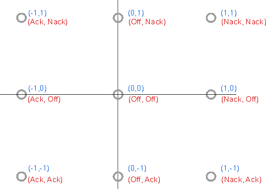
For example, the Subcarrier 1 IQ point in a PHICH group is at (1,0). For a signal with Normal PHICH duration, Subcarrier 1 contains the values for PHICH1 and PHICH5; therefore, PHICH1=Nack and PHICH5=Off.
Each despread PHICH IQ constellation point represents the Ack/Nack/Off values of two PHICH's, but does not accurately represent their BPSK symbol power levels.
You can also view the PHICH values in the Symbol Table. Possible PHICH values are from the set {0, 1, 3} which is mapped to {NACK, ACK, OFF}.
The PHICH sequence values are mapped to the hex digits in the following order for each PHICH group:
- For Normal CP, the order is PHICH index {0, 4, 1, 5, 2, 6, 3, 7}
- For Extended CP, the order is PHICH index {0, 2, 1, 3}
When the format is shown in binary, the same mapping order and values are used, but the even-indexed hex digits are truncated to two bits.
For example, a PHICH group (Normal CP) may show the value 010011 000011 1100 11110011... In this case, the first two bits, 01, indicate an ACK for PHICH0. The next four bits, 0011, indicate OFF for PHICH4. The next two bits, 00, indicate NACK for PHICH1. The next four bits, 0011, indicate OFF for PHICH5, and so on.
The actual ACK/NACK/Inactive information contained in PHICH can also be viewed in the DL Decode Info table.
Allocation (Ng)
PHICH can be autodetected or specified manually. When the radio button is selected, will be detected from PBCH.
is a higher layer parameter configured from the set {1/6, 1/2, 1, 2} that determines the number of PHICH groups per subframe.
The number of PHICH groups in a subframe is given by the equation for NgroupPHICH in Section 6.9 of 3GPP TS Technical Specification 36.211.
For example, a 5 MHz Megahertz: A unit of frequency equal to one million hertz or cycles per second. signal (25 RB Resource Block) with extended CP Length and Allocation = 1 will have 2*ceil(1*25/8) = 8 groups.
Duration
PHICH is a higher layer parameter configured either as or that tells the demodulator how many symbols per subframe are used by PHICH. PHICH Duration can be autodetected from PBCH when is selected.
For PHICH duration, there are 8 PHICH sequences in one PHICH group (and therefore 4 symbols). For PHICH duration, there are 4 PHICH sequences in one PHICH group (and therefore 2 symbols).
Each PHICH group is repeated three times in frequency. This is because PHICH is transmitted with a code rate of 1/3 (repetition coding).
Mi Definition (TDD only)
When is set to , the expected values of Mi are given by Table 6.9-1 in 3GPP TS 36.211.
When is set to , Mi is expected to equal 1 in all downlink subframes.
Mi is not applicable to FDD mode.
The Mi parameter determines how many PHICH groups there are in each downlink subframe for TDD mode. The values for Mi depend on the uplink-downlink configuration and are given by Table 6.9-1 in 3GPP TS 36.211.
However, 3GPP TS 36.141, section 6.1.2.6 specifies that Mi must be set to 1 when performing E-TM tests. This is to provide consistency between FDD and TDD test results.
See Also