BWP (5G NR/5G-Advanced)
The BWP panel contains the available DL Down Link (forward link: from base station to cell phone)-BWP/UL Up Link (reverse link: from cell phone to base station)-BWP carrier bandwidth part parameters. Following the 38.211 specification, the BWP panel contains a fixed collection of BWPs:
Uplink BWPs
Initial-UL-BWP 0 - Enables or disables the uplink carrier bandwidth part.
Default: enabled
UL-BWP 1-4 - Enables or disables the uplink carrier bandwidth part.
|
Resource allocations with different Numerology cannot be simultaneously enabled. |
|
|
An uplink bandwidth part (UL-BWP) and downlink bandwidth part (DL-BWP or SS/PBCH) cannot be simultaneously enabled in the same carrier definition. To configure both DL-BWPs and UL-BWPs, you must configure separate carrier definitions for both uplink and downlink by first selecting Mixed Link Direction and enabling Allow Multiple Carrier Definitions in the Carrier configuration panel. See the Carriers topic for more information. |
Default: disabled
Downlink BWPs
Initial-DL-BWP 0 - This checkbox enables or disables the initial downlink carrier bandwidth part.
Default: disabled
DL-BWP 1-4 - This checkbox enables or disables the downlink carrier bandwidth part.
Default: DL-BWP 1 enabled (all others disabled)
Initial-UL-BWP 0 - This checkbox enables or disables the initial uplink carrier bandwidth part, which is used for PDCCH decoding when scheduling uplink PUSCH.
Default: disabled
Uplink and Downlink BWP Parameters
ID - Displays the ID for the bandwidth part. The ID uniquely identifies the BWP and is used by the individual channels to associate themselves with particular BWPs.
Numerology - Sets the numerology for this bandwidth part. Numerology specifies the subcarrier spacing and cyclic prefix definition used for this bandwidth part.
See About Mixed Numerologies for information about multiple/mixed numerologies.
|
Numerology affects symbol duration and the number of subcarriers possible for a given carrier bandwidth. |
Default: µ = 1 :30 kHz kiloHertz: A radio frequency measurement (one kilohertz = one thousand cycles per second).
Choices: µ = 0 :15 kHz, µ = 1 :30 kHz, µ = 2 :60 kHz Normal CP 1) Contention period, or 2) Cyclic prefix, µ = 2 :60 kHz Extended CP, µ = 3 :120 kHz, µ = 4 :240 kHz, µ = 5 :480 kHz, µ = 6 :960 kHz
|
The µ = 4 :240 kHz numerology is not supported for DL-BWP. |
RB Offset - Sets the RB Offset for this bandwidth part.
A resource block (RB) consists of 12 contiguous subcarriers. The RB Number determines the contiguous amount of spectrum available to this bandwidth part starting from RB Offset within the containing Component Carrier. The maximum number of RB potentially available to this bandwidth part is determined by the Numerology of this bandwidth part and the maximum RB limit specified for the Component Carrier for that particular Numerology.
Default: 0 RB
Range: 0-(CC RB Bandwidth minus 1)
|
The RB Number setting for the PDSCH Physical Downlink Shared Channel physical channel cannot exceed the DL-BWP RB Number setting value, and is clipped accordingly. However, DL-BWP RB Offset is independent of the RB Offset settings for the physical channel. |
|
|
The RB Number settings for the PUSCH and PUCCH physical channels cannot exceed the UL-BWP RB Number setting value, and are clipped accordingly. However, UL-BWP RB Offset is independent of the RB Offset settings for the physical channel. |
RB Number - Sets the number of RB available in this bandwidth part.
A resource block (RB) consists of 12 contiguous subcarriers. The RB Number determines the contiguous amount of spectrum available to this bandwidth part starting from RB Offset within the containing Component Carrier. The maximum number of RB potentially available to this bandwidth part is determined by the Numerology of this bandwidth part and the maximum RB limit specified for the Component Carrier for that particular Numerology.
Default: Default value depends on maximum transmission Bandwidth, set to fully occupy carrier bandwidth.
Range: 1-(CC RB Bandwidth minus BWP RB offset)
|
The RB Number setting for the PDSCH physical channel cannot exceed the DL-BWP RB Number setting value, and is clipped accordingly. However, DL-BWP RB Offset is independent of the RB Offset settings for the physical channel. |
|
|
The RB Number settings for the PUSCH and PUCCH physical channels cannot exceed the UL-BWP RB Number setting value, and are clipped accordingly. However, UL-BWP RB Offset is independent of the RB Offset settings for the physical channel. |
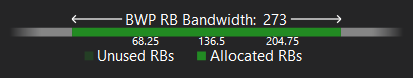
RB Allocation Diagram - The BWP RB Bandwidth/Allocation diagram is specific to each BWP. Click on a BWP's row to view its RB allocation diagram.
CORESETs (Downlink/DL-BWP Only)
Add CORESET - Adds a control-resource set (CORESET) . When a CORESET is added, a representative button is added at the top of the CORESET parameter group.
Remove CORESET - Removes the selected CORESET .
CORESET
CORESET - Displays the indexes of available CORESETs and allows the selection of a CORESET for editing.
CORESET ID - Sets the CORESET ID (controlResourceSetId) for the selected CORESET.
|
If CORESET ID 0 is selected, BWP ID is coerced to BWP0, all other CORESET parameters are grayed out and DMRS Scrambling ID is always -1, which means the Cell ID is used as the DMRS Scrambling ID. |
Default: 1
Choices: 0-(depends on the number of defined CORESETs)
BWP ID - Sets the BWP ID for the selected CORESET.
|
If BWP0 is selected, all other CORESET parameters are grayed out. |
Default: 0
Choices: BWP0, BWP1, BWP2, BWP3, BWP4
Symbol Number - Sets the number of symbols used for the selected CORESET. This parameter is grayed out if BWP ID is set to BWP0.
Default: 1
Choices: 1, 2, 3
DMRS Scrambling ID - Sets the PDCCH-DMRS-Scrambling ID for sequence generation. A value of -1 means “Not Configured.” In this case, the Cell ID is used for DMRS Scrambling ID. This parameter is grayed out if BWP ID is set to BWP0.
|
If CORESET ID 0 is selected, BWP ID is coerced to BWP0, all other CORESET parameters are grayed out and DMRS Scrambling ID is always -1, which means the Cell ID is used as the DMRS Scrambling ID. |
Default: -1
CCE To REG Mapping Type - Sets the mapping type for the selected CORESET. See the 38.211 specification for more information on interleaved and non-interleaved CCE-to-REG mapping. This parameter is grayed out if BWP ID is set to BWP0.
Default: Non-interleaved
Choices: Non-interleaved, Interleaved
RB Offset-r16 Configured - When selected, the RB Offset-r16 parameter is enabled to set the RB Offset of the first Allocated RB Groups (6RBs) relative to the start of DL-BWP.
This parameter is only visible when the selected CORESET's CORESET ID is non-zero. It is grayed out if BWP ID is set to BWP0.
RB Offset-r16 - When RB Offset-r16 Configured is selected (enabled), this parameter sets the offset (in RBs) of the first Allocated RB Groups (6RBs) relative to the start of DL-BWP. The range is 0 to 5 (0 being no offset and 5 being an offset of 5 RBs).
This parameter is only visible when the selected CORESET's CORESET ID is non-zero. It is grayed out if BWP ID is set to BWP0.
Default: 0
Range: 0-5
REG Bundle Size - When CCE To REG Mapping Type is set to Interleaved, this parameter sets the REG bundle size for the selected CORESET. See the 38.211 specification for more information on interleaved CCE-to-REG mapping and REG bundle size. This parameter is grayed out if BWP ID is set to BWP0.
Default: 6
Choices: 2, 3, 6
Interleave Size - When CCE To REG Mapping Type is set to Interleaved, this parameter sets the interleave size for the selected CORESET. See the 38.211 specification for more information on interleaved CCE-to-REG mapping and interleave size. This parameter is grayed out if BWP ID is set to BWP0.
Default: 2
Choices: 2, 3, 6
Shift Index Source - When CCE To REG Mapping Type is set to Interleaved, this parameter determines whether the Shift Index value is configured by the higher layer (From RRC) or from the Cell ID. See the 38.211 specification for more information on interleaved CCE-to-REG mapping and shift index. This parameter is grayed out if BWP ID is set to BWP0.
Default: Cell ID
Range: Cell ID, From RRC
Shift Index - When CCE To REG Mapping Type is set to Interleaved, this parameter sets the shift index for the selected CORESET. See the 38.211 specification for more information on interleaved CCE-to-REG mapping and shift index. This parameter is grayed out if BWP ID is set to BWP0.
Default: 0
Range: 0-65535
Allocated RB Groups (6RBs) - Sets the RB groups to be allocated for the selected CORESET (6 RBs per group). To set Allocated RB Groups to none, set the textbox to -1. This parameter is grayed out if BWP ID is set to BWP0.
Default: 0:44
Precoder Granularity Sets the precoder granularity (in frequency domain) of the selected CORESET. This parameter is grayed out if BWP ID is set to BWP0.
Default: Same as REG Bundle
Choices: Same as REG Bundle, All Contiguous RBs
See Also
5G NR/5G-Advanced Demod Properties Dialog Box