Antenna Pattern (5G NR/5G-Advanced)
The Antenna Pattern parameter group configures the antenna radiation pattern, which is used with Antenna Layout, Antenna Detection Threshold, Beam Patterns Include and Beam Weights to compute the simulated Beam Pattern.
The Antenna Pattern information refers to the element pattern, not the overall antenna pattern. This is used to configure the pattern for a single element, and the same pattern is applied to all elements. This configuration of a single element pattern applies to both Three Sector and User Defined Antenna Pattern types. If a .ant3D file contains multiple elements, the VSA software imports the pattern for the first element and applies it to all antenna elements.
specifies the antenna element radiation pattern.
Isotropic - Selects the isotropic antenna pattern type.
Three Sector - Selects the three sector antenna pattern type. When Three Sector is selected, the Three Sector Pattern parameters appear to configure the three sector pattern.
User Defined - Selects a user-supplied antenna pattern. When User Defined is selected, an Import button appears and the User Defined Pattern parameters appear for naming the pattern and viewing the details of the pattern.
Import - Click the Import button to open a dialog to select a user-supplied antenna pattern (.ant3D) file. This .ant3D file is generated using Keysight PROPSIM’s Channel Studio GCM antenna layout tool (F9860002A). The file contains 3D radiation data for an array of elements. In addition to the radiation pattern information, the file also contains antenna layout information with each element’s x,y,z location. The VSA software ignores the layout information when importing the file and expects the user to manually enter the same values under Antenna Layout.
By default, a .ant3D file is based on Global Coordinate System (GCS), in which case the antenna patterns are referenced to a common phase center. The VSA software, however, uses a Local Coordinate System (LCS), which requires each element pattern to be referenced to its own phase center. The GCM antenna layout tool can also be configured to generate an LCS .ant3D file for use with the VSA. In this case, the VSA uses the element geometry (x,y,x values) together with the LCS .ant3D file to calculate the beam direction accurately. See 3GPP TR 38.901 Section 7.1 for information on local and global coordinate systems and the transformation between LCS and GCS.
VSA does not import element geometry from the .ant3D file, only the radiation pattern. Users need to manually enter element coordinates in the Antenna Layout Configuration (in units of meters). If geometry values are in millimeters in the .ant3D file, convert them to meters before entering.
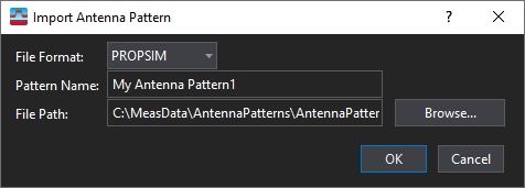
File Format - The file format is PROPSIM .ant3D. The Phi and Theta values have uniform step defined PhiStart, PhiStep, PhiStop, ThetaStart, ThetaStep, ThetaStop to describe the space range of the pattern.
Pattern Name - An editable field for adding a pattern name. This is the same setting as Name in the User Defined Pattern parameter group.
Range: Isotropic, Three Sector, User Defined
Default: Isotropic
Three Sector Pattern (Visible when Antenna Pattern is set to Three Sector)
specifies the front-to-back ratio for three-sector antenna patterns. The FrontToBack Ratio setting is visible when Three Sector is selected as the Antenna Pattern type. See 3GPP TR 38.820 V16.1.0 Section 7.2.4 for more information on array antenna model parameters.
Default: 30 dB
specifies the side lobe suppression (SLA) for three-sector antenna patterns. The SLA setting is visible when Three Sector is selected as the Antenna Pattern type. See 3GPP TR 38.820 V16.1.0 Section 7.2.4 for more information on array antenna model parameters.
Default: 30 dB
specifies the horizontal half power beam width (HPBW), in degrees, for three-sector antenna patterns. The Horizontal HPBW setting is visible when Three Sector is selected as the Antenna Pattern type. See 3GPP TR 38.820 V16.1.0 Section 7.2.4 for more information on array antenna model parameters.
Default: 90 deg
specifies the vertical half power beam width (HPBW), in degrees, for three-sector antenna patterns. The Vertical HPBW setting is visible when Three Sector is selected as the Antenna Pattern type. See 3GPP TR 38.820 V16.1.0 Section 7.2.4 for more information on array antenna model parameters.
Default: 90 deg
specifies the scan angle for three-sector antenna patterns. Assuming the Scan Angle and Downtilt Angle are accomplished by mechanical rotation, when calculating the overall beam pattern in GCS (Global Coordinate System), the coordinate is first converted from GCS to LCS (Local Coordinate System), then the three sector antenna pattern defined in LCS is used to calculate the overall beam pattern. The Scan Angle setting is visible when Three Sector is selected as the Antenna Pattern type. See 3GPP TR 38.820 V16.1.0 Section 7.2.4 for more information on array antenna model parameters.
Default: 0 deg
specifies the downtilt angle for three-sector antenna patterns. Assuming the Scan Angle and Downtilt Angle are accomplished by mechanical rotation, when calculating the overall beam pattern in GCS (Global Coordinate System), the coordinate is first converted from GCS to LCS (Local Coordinate System), then the three sector antenna pattern defined in LCS is used to calculate the overall beam pattern. The Downtilt Angle setting is visible when Three Sector is selected as the Antenna Pattern type. See 3GPP TR 38.820 V16.1.0 Section 7.2.4 for more information on array antenna model parameters.
Default: 90 deg
User Defined Pattern (Visible when Antenna Pattern is set to User Defined)
is an editable field for adding a pattern name. This is the same setting as Pattern Name in the Import Antenna Pattern dialog.
displays the first Phi value in the imported user defined antenna pattern. The Phi Start setting is visible when User Defined is selected as the Antenna Pattern type.
displays the last Phi value in the imported user defined antenna pattern. The Phi Stop setting is visible when User Defined is selected as the Antenna Pattern type.
displays the step between the adjacent Phis in the imported user defined antenna pattern. The Phi Step setting is visible when User Defined is selected as the Antenna Pattern type.
displays the first Theta value in the imported user defined antenna pattern. The Theta Start setting is visible when User Defined is selected as the Antenna Pattern type.
displays the last Theta value in the imported user defined antenna pattern. The Theta Stop setting is visible when User Defined is selected as the Antenna Pattern type.
displays the step between the adjacent Thetas in the imported user defined antenna pattern. The Theta Step setting is visible when User Defined is selected as the Antenna Pattern type.
See Also