Configure Rectangular Array... (5G NR/5G-Advanced)
Configure Rectangular Array... (Rectangular Antenna Array dialog) contains parameters for setting the number of antenna groups within the rectangular array and configuring the panels and elements (antennas) within each group.
When configuring the antenna group, Channel Index 1 starts from the top left antenna. The index increments down the first column and continues to the next column, as shown in the example below. Local beam pattern coordination origin is the symmetric point of each antenna group.
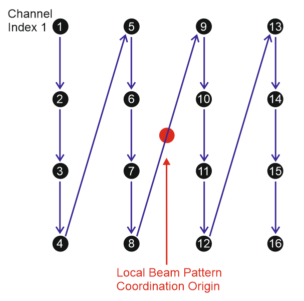
Example of a 64 channel cross-polarized rectangular antenna panel array configuration:
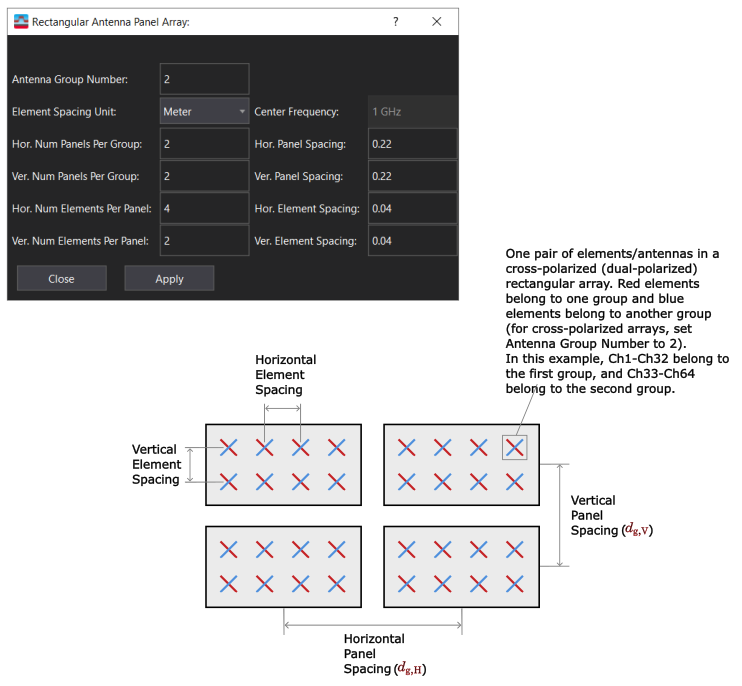
specifies the number of antenna groups/polarizations in the array. If all of the antennas in the array have the same polarization, set the antenna group number to 1. For cross-polarized (dual-polarized) antenna arrays, set Antenna Group Number to 2. The first half of the channels in the user input antenna layout (e.g., Ch1-Ch32) are assigned to group/polarization 1 and the second half (e.g., Ch33-Ch64) are assigned group/polarization 2. The two groups share the same panel/element configuration; therefore, all configurations on this page apply to both polarizations.
specifies unit of measure used in the Hor. Element Spacing, Ver. Element Spacing, Hor. Panel Spacing and Ver. Panel Spacing settings.
Range: Wavelength, Meter
Default: Wavelength
specifies the center frequency of the antenna array.
specifies the horizontal number of panels per antenna group. Possible values are in the range 1-64, depending on the hardware configuration and the distribution of antennas for each antenna group.
Range: 1-64
Default: 1
specifies the horizontal distance between panels. This parameter is specified in units of Wavelength or Meter, depending on the Element Spacing Unit setting.
Default: 0.5 (Wavelength)
specifies the vertical number of panels per antenna group. Possible values are in the range 1-64, depending on the hardware configuration and the distribution of antennas for each antenna group.
Range: 1-64
Default: 1
specifies the vertical distance between the panels. This parameter is specified in units of Wavelength or Meter, depending on the Element Spacing Unit setting.
Default: 0.5 (Wavelength)
specifies the horizontal number of antennas per panel. Possible values are in the range 1-64, depending on the hardware configuration and the distribution of antennas for each panel.
Range: 1-64
Default: 1
specifies the horizontal distance between the antennas in each panel. This parameter is specified in units of Wavelength or Meter, depending on the Element Spacing Unit setting.
Default: 0.5 (Wavelength)
specifies the vertical number of antennas per panel. Possible values are in the range 1-64, depending on the hardware configuration and the distribution of antennas for each panel.
Range: 1-64
Default: 1
specifies the vertical distance between the antennas in each panel. This parameter is specified in units of Wavelength or Meter, depending on the Element Spacing Unit setting.
Default: 0.5 (Wavelength)
See Also