Displaying an EvT Trace with Band Power Markers (TEDS)
To display an Error Vector Time trace with Band Power Markers using a test signal for TEDS Normal Uplink, 50kHz, 16QAM:
- Load the demo signal (see Loading a TEDS Demo Signal).
- Select TEDS demodulation (see Selecting TEDS Demodulation).
- In the tab of the dialog box (see Displaying TEDS Demod Properties Dialog Box ), select a channel bandwidth of 50kHz. The must be selected before a can be used.
- Click . The VSA will then set certain parameters based on a Normal Uplink slot format / 50kHz channel bandwidth. The parameter settings are listed in Using Standard Setups/Presets.
- In the tab of the TEDS demod properties dialog box (see Displaying TEDS Demod Properties Dialog Box ), select 16QAM for the modulation type (if necessary).
-
Click within a trace, and then select to view the composite Error Vector Time trace. To scale the trace, select .
-
Configure Band Power markers
-
Click
-
In the tab of the dialog, select the checkbox.
-
Set to
-
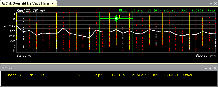
Move the band power marker to the desired location by using the mouse to click and drag the marker or by setting the and in the dialog. For example, Center = 15 sym and Span = 5 sym.
-
-
Review the Band Power information at either the top of the trace (currently selected marker) or in the marker readout window.
See Also