Slots and Symbols (TEDS)
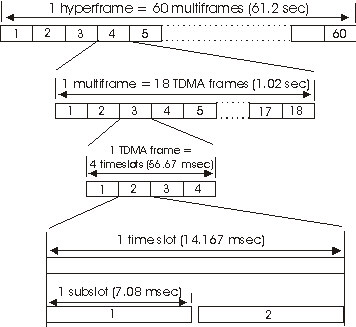
The image below is a representation of the TDMA Time Division Multiple Access: A technology for digital transmission of radio signals between, for example, a mobile telephone and a radio base station. In TDMA, the frequency band is split into a number of channels which in turn are stacked into short time units so that several calls can share a single channel without interfering with one another. Networks using TDMA assign 6 timeslots for each frequency channel. TDMA is also the name of a digital technology based on the IS-136 standard. TDMA is the current designation for what was formerly known as D-AMPS. structure. The hyperframe level defines the top-level frame hierarchy. One hyperframe is subdivided into 60 multiframes and lasts 61.2 sec. One multiframe is subdivided in 18 frames and has a duration of 1.02 sec. The eighteenth frame in a multiframe is a control frame. One frame is subdivided into 4 time slots and has a duration of 170/3 msec or 56.67 msec. The time slot interval is a time interval of 85/6 msec or 14.167 msec (Normal Downlink and Normal Uplink). The uplink timeslots may be subdivided into 2 subslots with durations of 85/12 msec or 7.083 msec (Control Uplink and Random Access).

The Normal Downlink slot format applies to the air interface between fixed network equipment (basestation) and subscriber units. The downlink transmission mode is continuous. You can view this slot as a time record using the Main Time trace. The time slot is a time interval of 85/6 msec or 14.167msec.
The Normal Uplink slot format applies to the air interface between subscriber units and the fixed network equipment (basestation). Unlike the Downlink slot format, which specifies continuous modulation of slot after slot, the Normal Uplink specifies a burst of 1 or more slots. With this slot format, subscriber units "take turns" sending data to a single basestation. For example, the first slot might be sent by subscriber A, the next slot by subscriber B, the next by subscriber C, and so forth. You can view this slot as a time record using the Main Time trace.
The Random Access slot format applies to the air interface between subscriber units and the fixed network equipment (basestation). Unlike the Downlink slot format, which specifies continuous modulation of 14.167msec slot after slot, and unlike the Normal Uplink slot format, which specifies burst modulation of single 14.167msec slots, the Random Access 14.167msec slot is divided into separate 7.083msec subslots where each subslot operates independently. The 25kHz channel bandwidth allows for 2 sub-slots You can view this slot as a time record using the Main Time trace. See TEDS Subcarriers for more information on slots, subcarriers and symbols.
The Control Uplink slot format is the same physically as the Random Access slot format but where Random Access is used for initiating a call, Control Uplink is used for sending control information. Thus the Control Uplink 14.167msec slot is divided into separate 7.03msec subslots where each subslot operates independently, like the Random Access slot format. The 25kHz channel bandwidth allows for 2 sub-slots; the 50kHz channel bandwidth allows for 4-sub-slots; the 100kHz channel bandwidth allows for 6 sub-slots, and the 150kHz channel bandwidth allows for 8 sub-slots, all operating independently.
See Also
