Displaying a Composite Symbols Table (TEDS)
To display the composite Symbol Table using a test signal for TEDS Normal Uplink, 50kHz, 16QAM:
- Load the demo signal (see Loading a TEDS Demo Signal).
- Select TEDS demodulation (see Selecting TEDS Demodulation).
- In the tab of the dialog box (see Displaying TEDS Demod Properties Dialog Box ), select a channel bandwidth of 50kHz. The must be selected before a can be used.
- Click . The VSA will then set certain parameters based on a Normal Uplink slot format / 50kHz channel bandwidth. The parameter settings are listed in Using Standard Setups/Presets.
- In the tab of the TEDS demod properties dialog box (see Displaying TEDS Demod Properties Dialog Box ), select 16QAM for the modulation type (if necessary).
- Click within a trace, and then select to view a table of the symbols
for the composite signal.
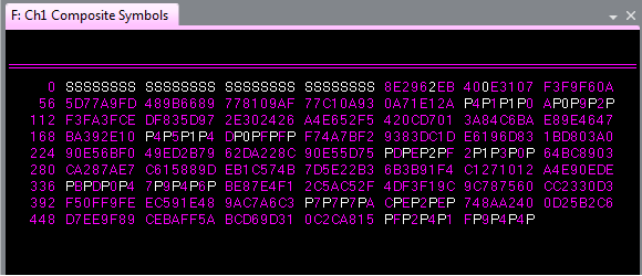
In the Symbol Table, the sync, pilot, and header symbols are in white. Sync (S) symbols are first, followed by an interspersing of Pilot (P) and Header symbols. The Header symbols appear as data values when Include - Header Symbols is selected (default). These data values are limited to hex 0, 1, 2, 3 since the data is always QPSK Quadrature phase shift keying. To view Header symbols as an "H", clear Include - Header Symbols.
The remaining symbols in color are the Data symbols. The quantity and format of the symbols appearing in this table depend on the Modulation Type format (the above example is for 16QAM), as well as Trace properties (hex or binary display using ). Place a marker on a symbol value using to clarify the display.
See Also